


Pipeline built-in electric heating complete set
The technology of this product is to directly penetrate the MI heating cable into the pipeline, which makes full use of the good mechanical and anti-corrosion performance of the MI heating cable. It is named "built-in" to distinguish it from the traditional electric heating installation outside the pipeline.
Classification:
Key words:
Pipeline built-in electric heating complete set
- Description
- Specification
- parameter
- output power
- Application
-
- Commodity name: Pipeline built-in electric heating complete set
- Commodity ID: 1329827727963475968
The technology of this product is to directly penetrate the MI heating cable into the pipeline, which makes full use of the good mechanical and anti-corrosion performance of the MI heating cable. It is named "built-in" to distinguish it from the traditional electric heating installation outside the pipeline.
The technology of this product is to directly penetrate the MI heating cable into the pipeline, which makes full use of the good mechanical and anti-corrosion performance of the MI heating cable. It is named "built-in" to distinguish it from the traditional electric heating installation outside the pipeline.
MI heating cable penetrates directly into the pipeline, and 100% of the heat is input into the pipeline, heating or maintaining the temperature of the gas or liquid medium in the pipeline. It is especially suitable for heating the gathering and transportation pipelines of oil wells in the low-yield period, promoting the flow of crude oil in the pipelines, reducing well pressure and ensuring oil production.
can also replace wellhead heaters; the advantage is: once there is a pipeline condensing and blocking accident, it can be used for a long time continuous electric heating, and the condensed medium in the pipeline is gradually melted linearly, making the pipeline faster To reopen.
The required use condition of is that the medium flowing in the pipeline is determined to be in a laminar flow state. The turbulent flow state requires special measures, and there should be no straight valves in the middle of the pipeline.
-
Model description and performance characteristics
1. Model description
Built-in electric heater

Performance characteristics
High thermal efficiency: The heating body of the built-in electric heater is placed in the pipe, fully contacted with the internal medium, and 100% of the heat generated can be in the pipe, so the thermal efficiency is high.
Stable performance: MI heating cables and temperature measuring cables are made of inorganic insulating materials, and their physical and chemical properties are quite stable at their rated operating temperature.
Long service life: The metal sheath of MI heating cable and temperature measuring cable is sealed, seamless, mechanically strong, and there is no thermal aging. The choice of medium corrosion-resistant sheath material can guarantee its long-term service life of more than 30 years .
Easy installation: The product is built into the pipeline without internal fixation, and the external connection is simple. (The state of turbulence is discussed separately)
Safe and reliable: The complete set of products is equipped with reliable electrical protection measures, and its automated operation is safer, explosion-proof and reliable, and fully meets the requirements of oil and gas field HSE management standards.
-
3. Main parameters
3.1 Built-in electric heater (three-core element heating cable as an example)
No.
Model
Rated voltage
(V)
Nominal power
(W)
Reference outer diameter(mm)
Heating length
(m)
1
NDRQ/S-9K/3/380/300
380
9000
6.3
300
2
NDRQ/S-12K/3/380/450
380
12000
6.8
450
3
NDRQ/S-15k/3/380/500
380
15000
6.7
500
4
NDRQ/S-18k/3/380/650
380
18000
7.2
650
5
NDRQ/S-25k/3/380/400
380
25000
7.2
750
6
NDRQ/S-30k/3/380/300
380
30000
8.5
800
7
NDRQ/B-40K/3/380/300
380
40000
10.3
1000
8
NDRQ/B-50K/3/380/450
380
50000
10.7
1200
-
Working principle
The built-in electric heater is a purely resistive electric heating load. The heat energy is released through the metal sheath of the MI heating cable and the surrounding medium to realize the heating or heat preservation of the medium. The whole process is completed in the conveying pipeline. The electrical principle block diagram of the system is shown as in Fig. 2.
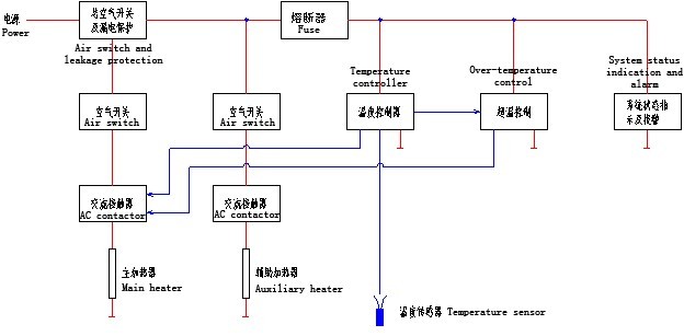
Figure 2 Electrical schematic diagram
-
Installation steps:
1. Check the qualified performance of all built-in electric heater equipment.
2. Assemble the pay-off stand. Set up the pipeline threading tractor.
3. At the selected point of the oil pipeline outside the wellhead (the vertical part above the ground), an arc-shaped opening is cut by gas cutting according to the arc shape of the DN55; 30-degree miter pipe provided by the supplier. Grind the groove and repair the gas cutting burr inside the pipe, and weld with the 30-degree mitered pipe.
4. Place the looped element MI heating cable and temperature measuring cable on the pay-off rack respectively (the end of the product is coiled on the outside when the product leaves the factory), and first pass the tail tip of the heating cable into the spherical pipe passer On the screw holes.
5. Slowly penetrate the pipeline tow bar into the pipeline and bring in the traction wire. Until it reaches the predetermined outlet of the end of the pipeline.
6. Connect the traction wire rope to the spherical pipe threader.
7. Rotate the pay-off stand, slowly release the componentized MI heating cable and straighten it, so that it will slowly and smoothly penetrate the pipe under the traction of the steel cable. (If the distance is too long, intercom communication equipment is required to coordinate and contact the command.) Note: If the temperature measurement at the end of the pipe is used, the temperature measurement cable needs to be passed through the spherical pipe piercer and brought into the pipe at one time.
8. There is also a construction method (referred to as B method, suitable for pipelines within 500m), which is to insert the pipe draw rod head and the spherical pipe piercer (specially made by the supplier), and the pipeline draw rod is brought into the pipeline at the same time Component heating cables, etc., after laying in place, withdraw the pipeline tow rod, the head of the pipeline tow rod and the spherical pipe piercer will be automatically separated, and the spherical pipe piercer will stay in the pipe.
9. The current pipeline drawbar is 500 meters long, so the pipe excavation relay method should be used for the part that exceeds the length. (The pipe diameter is large, and the distance is long. Air blowing, water pressure top, or rocket payoff can be used)
10. The temperature measuring cable and the heating cable enter the pipe in the same direction. Bundle the temperature measurement cable and fix it on the heater cable when you are in the same industry. The best distance between the bindings is 500mm, and the cable should be bundled while piercing the tube until the piercing is completed. (The situation with auxiliary electric heater is the same as this)
11. Check the insulation of the built-in electric heater. If the insulation is good, you can proceed to the next operation, otherwise, you should do the treatment to restore the insulation in time.
12. Place a gasket on the flange cover, and pass the flange cover of the oil channel mitre pipe through all heating cables and temperature measurement cables. Then tighten the mechanical seals of the heating cables and temperature measuring cables one by one.
13. Tighten the flange cover with bolts. (Some of the wires are too long, bend and store in the thick tube in advance)
14. Open the wellhead oil valve, loosen the bleed screw, and discharge the air in the 30° miter pipe.
15. Install the explosion-proof junction box body on the flange cover.
16. Test the insulation of the built-in electric heater again.
17. Install the temperature control box in place.
18. Lay and connect all cables between the temperature control box and the junction box. Among them, the power cable should select the appropriate cross section and core number according to its current carrying capacity and actual load rated current.
19. Connect the external cables, etc. with the leads in the junction box according to the provided drawings (in the packing box).
20. After commissioning and trial operation, complete all the follow-up work to clear the site.
Installation notes:
1. If opening relay holes, you can choose wasteland or ridge to reduce the impact on farmland crops.
2. The relay hole should be opened by a tapping machine, and the complete orifice plate can still be welded back to the opening.
3. When feeding the heating cable into the pipe, the heating cable should be slow and evenly applied. If there is an obstacle, do not apply force. Return a little and then feed it slowly. (When using the B method, pay attention to the rod and the heating cable must be retreated synchronously when returning!)
4. The control box should be placed in a place that is easy to manipulate and easy to observe.
5. The control box should be installed vertically on the wall or on the ground, and the enclosure should be electrically grounded.
6. The distance between the control box and the release point of combustible substances should meet the requirements of relevant regulations.
7. Cables entering the junction box and temperature control box should wear protective metal hoses.
8. The MI heating cable of the construction component can not be bent hard or excessively.
Debugging and operation
Before debugging, conduct a general test of the insulation of the heating cable, and its value should be 10MΩ/500V or more, and check the correctness of the wiring. After the above preparations are completed, you can power on and debug.
The steps to start the system are as follows:
1. Turn on the power supply of the control box.
2. Open the box door and close the main circuit breaker and main circuit breaker. At this time, the red light (system power) is on.
3. Set the desired temperature on the panel of the temperature controller, and then turn the “Auto/Manual” knob to “Auto“, and the system enters normal operation. When the temperature measured by the temperature controller is lower than the set temperature lower limit, the contactor is closed, the heating cable is working, and the green light is on. When the measured temperature reaches the upper limit of the set temperature, the contactor opens, the heating cable stops working, and the red light is on. When the measured temperature exceeds the set alarm temperature value, the alarm will sound and the yellow light will be on.
4. When auxiliary heating is needed, turn on the auxiliary heater breaker, and then turn the auxiliary heating switch on the operation panel to the “run” position to start auxiliary heating. When the heating power is above 30Kw, it is equipped with a phase ammeter.
The steps to stop the system are as follows:
1. Disconnect the circuit breakers of the main heater and auxiliary heater.
2. Cut off the main power supply to the control box.
Note: When the yellow light is on, it means that the system has generated an over-temperature alarm, and the system will self-lock to make the contactor in a disconnected state. At this time, the cause of the over-temperature should be found in time, and the fault should be eliminated. After troubleshooting, you must turn the “reset” knob to “reset” before it can be put into operation again. Warning: The operation and maintenance personnel must strictly follow the operation instructions to protect the normal operation of the equipment.


WRITE A MESSAGE TO US
If you are interested in our products, please leave your email, we will contact you as soon as possible, thank you!