


Flame-retardant wire and cable
This product is suitable for transmission of electric energy in power lines with a rated voltage of 0.6/1KV and below. Resistant wires and cables are difficult to catch fire and have the ability to prevent or delay the spread of flames. They are suitable for laying in a variety of occasions where cables have flame-retardant requirements, such as high-rise buildings, hotels, hospitals, subways, nuclear power plants, power plants, mines, and petroleum. , Chemical industry, etc.
Classification:
Key words:
Flame-retardant wire and cable
- Description
- Model and specification
- Usage characteristics
- Parameter
- Transportation
-
- Commodity name: Flame-retardant wire and cable
- Commodity ID: 1329827697869344768
This product is suitable for transmission of electric energy in power lines with a rated voltage of 0.6/1KV and below. Resistant wires and cables are difficult to catch fire and have the ability to prevent or delay the spread of flames. They are suitable for laying in a variety of occasions where cables have flame-retardant requirements, such as high-rise buildings, hotels, hospitals, subways, nuclear power plants, power plants, mines, and petroleum. , Chemical industry, etc.
This product is suitable for power transmission in power lines with a rated voltage of 0.6/1KV and below. Resistant wire and cable have the ability to catch fire and prevent or delay the spread of flame. It is suitable for laying in a variety of occasions where the cable has flame-retardant requirements, such as high-rise buildings, hotels, hospitals, subways, nuclear power plants, power plants, mines, and petroleum. , Chemical industry, etc.
Product implementation standards:GB/T19666-2005, GB/T5023-2008, GB/T12706.1-2008, GB/T9330-2008Instructions for flame-retardant wires and cables
Flame-retardant wire and cable refers to being burned under the specified test conditions, so that the flame spread is only within a limited range. After the fire source is removed, the residual smoke and residual burn can extinguish the cable by itself within a limited time
Flame retardant grade of flame retardant wire and cable
The burning of finished wires and cables is divided into single burning test and bundle burning test.
Single burning test method: Take the vertical support of the specimen with the specified length, place the rubberized kraft paper "flame indicator" on the upper part of the specimen, and place the surgical cotton ball under the specimen. Use a blowtorch to supply fire to the specimen for 15s, Stop for 15s. After repeated 5 cycles, if the "flame indicator" burns more than 25%, the burning drops ignite the cotton ball, and the flame lasts for more than 60s, it will be judged as unqualified, otherwise it is qualified.
Bundle burning test method: The cables are arranged in a bundle on a vertical ladder frame, and the sample is supplied with a torch for a specified time from the bottom to the top. After stopping the fire supply for 1 hour, measure the height of the carbonized part of the sample. If the height of the carbonized part does not exceed 2.5 meters, it is judged as qualified, otherwise it is unqualified.
According to the test conditions specified in GB/T18380.3-2002, flame-retardant wires and cables are divided into four levels: A, B, C, and D
Table 1Flame retardant grade
Fire temperature
Fire time
The volume of non-metallic materials for laying cables in bundles
Charring height
Self-extinguishing time
Applicable products
A
≥815℃
40min
≥7L/m
≤2.5m
≤1h
Flame retardant cable
B
≥815℃
40min
≥3.5L/m
≤2.5m
≤1h
Flame retardant cable
C
≥815℃
20min
≥1.5L/m
≤2.5m
≤1h
Flame retardant cable
D
≥815℃
20min
≥0.5L/m
≤2.5m
≤1h
Flame retardant insulated wire
-
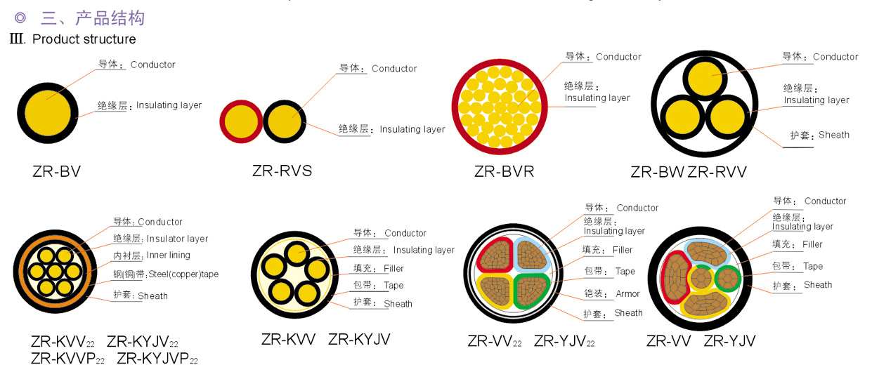
Representation of flame-retardant wire and cable products
The model representation method of the flame-retardant wire and cable: The model of the flame-retardant wire and cable is added ○-□ before the model of the ordinary cable. 〇- is the flame-retardant code and represented by Z, □- is the flame-retardant grade code, and the flame-retardant grade ABCD is used Means.
Products are expressed by model, rated voltage, core number, nominal cross section and the number of this standard.
For example: Rated voltage 450/750V flame-retardant PVC wire, single core, 4mm2, expressed as ZB-BV 450/750V 1*4 Q/TEC16.03-2005
Rated voltage 600/1000V flame-retardant Class B XLPE insulated PVC sheathed power cable, 3-core, 240mm2, denoted as ZB-YJV 600/1000V 3*240 Q/TEC16.03-2005See the table for the model and name of the cable
Model
Name
Flame retardant rating
Core number
Cross section
mm2Rated voltage
vZ-BV
PVC insulated flame retardant wire with copper core
A、B、C、D
1
1.5-400
450/750
Z -BVV
PVC insulated flame retardant round cable with copper core and sheath A、B、C、D
1-5
1.5-35
300/500
Z -BVVB
PVC insulated flame retardant flat cable with copper core and PVC sheath
A、B、C、D
2,3
0.75-10
300/500
Z -BVR
PVC insulated flame retardant flexible cable with copper core
A、B、C、D
1
2.5-70
450/750
Z -RVS
PVC insulated flame retardant stranded connecting flexible cable with copper core
A、B、C、D
1
0.75-2.5
300/300
Z -RV
Sheathless flame retardant flexible cable with copper core A、B、C、D
1
1.5-240
450/750
Z -KVV
PVC insulated flame retardant control cable with PVC sheath A、B、C、D
2-61
1-10
450/750
Z -KVV22
PVC insulated flame retardant control cable with PVC sheath and steel tape armoring
A、B、C、D
2-61
1-10
450/750
Z -KVVP2
PVC insulated flame retardant control cable with PVC sheath and copper tape shielding
A、B、C、D
2-61
1-10
450/750
Z -KVVP2-22
PVC insulated flame retardant control cable with PVC sheath, copper tape shielding and steel tape armoring
A、B、C、D
2-61
1-10
450/750
Z -KYJV
Crosslinked polyethylene insulated flame retardant control cable with PVC sheath A、B、C、D
2-61
1-10
450/750
Z -KYJV22
Crosslinked polyethylene insulated flame retardant control cable with PVC sheath and steel tape armoring
A、B、C、D
2-61
1-10
450/750
Z -KYJVP2
Crosslinked polyethylene insulated flame retardant control cable with PVC sheath and copper tape shielding
A、B、C、D
2-61
1-10
450/750
Z -KYJVP2-22
Crosslinked polyethylene insulated flame retardant control cable with PVC sheath, steel tape armoring and copper tape shielding
A、B、C、D
2-61
1-10
450/750
Z -VV
PVC insulated flame retardant cable with PVC sheath A、B、C、D
1-5
1.5-800
600/1000
Z -VV22
PVC insulated flame retardant cable with PVC sheath and steel tape armoring
A、B、C、D
1-5
1.5-400
600/1000
Z -YJV
Crosslinked polyethylene insulated flame retardant cable with PVC sheath
A、B、C、D
1-5
1.5-800
600/1000
Z -YJV22
Crosslinked polyethylene insulated flame retardant cable with PVC sheath and steel tape armoring
A、B、C、D
1-5
1.5-400
600/1000
-
This product is suitable for power transmission in power lines with a rated voltage of 0.6/1KV and below. The resistance wire and cable is difficult to catch fire and has the ability to prevent or delay the spread of flame. It is suitable for a variety of occasions where the cable has flame retardant requirements
Using features
The rated voltage U0/U of the flame-retardant cable is 0.6/1KV, the rated voltage U0/U of the flame-retardant control cable is 450/750V, and the rated voltage U0/U of the flame-retardant wire and cable is 450/750V and below.
The long-term allowable working temperature of PVC insulated cables does not exceed 70℃, and the long-term allowable working temperature of XLPE insulated cables does not exceed 90℃
The ambient temperature during installation should not be lower than 0°C.
Minimum bending radius during cable installation
The outer diameter (D) of the flame-retardant wire is less than 25mm, the allowable bending radius of the cable should not be less than 4D, the outer diameter (D) is 25mm and above, and the allowable bending radius of the cable should not be less than 6D.
Flame-retardant and fire-resistant control cables: cables without armor layers should be no less than 6 times the outer diameter of the cables, cables with armored or copper tape shielding structures should be no less than 12 times the outer diameter of the cables.
The minimum bending radius of flame-retardant and fire-resistant power cables is shown in Table 3Single core cable
Multi-core cable
Item Item
Unarmored
Armored
Unarmored
Armored
Minimum bending radius during installation
20D
15D
15D
12D
D-Outer diameter of the cable
Table 4 Nominal cross-section of neutral conductor of multi-core cable
Nominal cross section of main insulated core conductor /min2
Nominal cross section of neutral conductor /min2
3+1, 3+2, 4+1 core
3+1, 3+2, 4+1 Cores4, 5 cores
4. 5 Cores4
2.5
4
6
4
6
10
6
10
16
10
16
25
16
25
35
16
35
50
25
50
70
35
70
95
50
95
120
70
120
150
70
150
185
95
185
240
120
240
300
150
300
400
185
400
The conductive core of the single-core cable is round, and those of 16mm2 and above can be pressed tightly. For multi-core cables with a cross-section of 35mm2 and below, the core should be round, and those with a cross-section of 50mm2 and above should be fan-shaped, tile-shaped or semicircular. The fourth core (neutral core) in a four-core cable can be round or fan-shaped. The neutral wire of a five-core cable can be round or tile-shaped. Those with a diameter of 6mm2 and below are allowed to be composed of a single conductor, and those with a diameter of 10mm2 and above are composed of multiple single wires. The shaped conductor (sector, tile or semicircle) should be tightly pressed.
Main performance
The finished wire should be able to withstand 5 cycles of vertical burning test without transmitting flame. After the test, the continuous burning time of the sample should not exceed 1h. The finished cable should be subjected to a bundled cable burning test. After the test, the height of the scorched or affected part of the cable should not exceed 2.5m above the point of action of the flame.
The wire and cable should withstand the low-temperature winding test or low-temperature impact test at -15℃. After the test, there should be no visible cracks on the surface of the sample.
The insulation volume resistivity of the finished wire at 70℃ should be greater than 1*1010Ω/cm.
The finished flame-retardant and fire-resistant wire should be able to withstand the 2.5KV AC voltage test without breakdown in 5 minutes. The finished flame-retardant and fire-resistant control cable should be able to withstand the 3KV AC voltage test without breakdown in 5 minutes. The finished flame-retardant and fire-resistant power cable should be able to withstand the 3.5KV AC voltage test, and the flame-retardant and fire-resistant wire and cable should not be broken for 5 minutes. The flame-retardant and fire-resistant wire and cable are made of highly flame-retardant polyvinyl chloride plastic, and the oxygen index is greater than 30%. The cables are the same.
Cable specifications and reference dataThe specifications, structural dimensions and weight of the flame-retardant wire and cable products are according to the common type and similar products.
Selection points of flame-retardant cablesWhen wires and cables are laid in bundles, flame-retardant wires and cables should be used.
Method for selecting flame retardant grade of flame retardant cable:
Calculate the total volume of non-metallic materials of wires and cables according to Table 5 to Table 7, and then determine the flame retardant grade according to Table 1.
For cables laid in the same channel, cables of the same flame-retardant grade should be selected. Flame-retardant and non-flame-retardant cables should not be laid in the same channel. For cables laid in a box with a cover and a cable trench with a cover, if measures such as blocking and water blocking have been taken to prevent flame extension, the first-class flame-retardant requirement can be reduced. The flame-retardant cable must indicate the flame-retardant level. Those who indicate the level shall be regarded as C level. -
Table 5 Reference table for non-metallic content of 450/750V PVC insulated wires
Cross section
mm2Diameter
mmNonmetal content
l/mCross section
mm2Diameter
mmNonmetal content
l/mCross section
mm2Diameter
mmNonmetal content
l/mCross section
mm2Diameter
mmNonmetal content
l/m1.5
3.4
0.0076
16
8
0.0342
95
17
0.1319
300
29.5
0.3831
2.5
4.2
0.0113
25
9.8
0.0504
120
19
0.1634
400
33.5
0.4810
4
4.8
0.0141
35
11
0.0600
150
21
0.1962
6
5.4
0.0169
50
13
0.0827
185
23.5
0.2485
10
6.8
0.0263
70
15
0.1066
240
26.5
0.3113
Table 6 Reference table for non-metallic content of 0.6/1KV PVC insulated unarmored cables
1 core
3 cores
(3+1) cores
Cross section
mm2Diameter
mmNonmetal content
l/mCross section
mm2Diameter
mmNonmetal content
l/mCross section
mm2Diameter
mmNonmetal content
l/m1.5
5.8
0.0294
1.5
10.4
0.0878
2.5
6.2
0.0327
2.5
11.3
0.0975
2.5
11.9
0.1099
4
7.1
0.0416
4
13.2
0.1238
4
13.7
0.1369
6
7.6
0.0461
6
14.3
0.1372
6
15.2
0.1572
10
8.9
0.0576
10
17.0
0.1742
10
17.8
0.1957
16
9.6
0.0643
16
18.6
0.1961
16
20.0
0.2295
25
11.2
0.0830
25
22.5
0.2910
25
23.7
0.3181
35
12.2
0.0926
35
24.6
0.3203
35
25.5
0.3448
50
14.0
0.1161
50
25.3
0.3481
50
28.6
0.4166
70
15.8
0.1386
70
28.4
0.4069
70
32.3
0.4864
95
18.0
0.1753
95
32.4
0.5098
95
37.3
0.6298
120
19.4
0.1918
120
35.4
0.5745
120
40.5
0.7090
150
21.6
0.2343
150
39.0
0.6911
150
44.4
0.8489
185
23.8
0.2809
185
43.0
0.8230
185
49.7
1.0244
240
26.5
0.3323
240
48.8
1.0379
240
56.0
1.2635
300
31.3
0.4284
300
53.0
1.2344
300
62.2
1.5166
Continued Table 6
4 cores
5 cores
(4+1) cores
(3+2) cores
Cross section
mm2Diameter
mmNonmetal content
l/mCross section
mm2Diameter
mmNonmetal content
l/mCross section
mm2Diameter
mmNonmetal content
l/mCross section
mm2Diameter
mmNonmetal content
l/m1.5
11.2
0.1012
1.5
12.0
0.1158
2.5
12.2
0.1128
2.5
13.1
0.1294
2.5
12.9
0.1099
2.5
13.3
0.1474
4
14.3
0.1456
4
15.5
0.1717
4
15.0
0.1369
4
15.0
0.1723
6
15.5
0.1646
6
16.9
0.1908
6
16.6
0.1572
6
16.3
0.1913
10
18.6
0.2066
10
20.3
0.2410
10
19.6
0.1957
10
18.9
0.2290
16
20.4
0.2329
16
22.4
0.2716
16
22.4
0.2295
16
22.0
0.2732
25
24.7
0.3356
25
27.1
0.3932
25
26.2
0.3181
25
25.4
0.3596
35
27.1
0.3712
35
30.0
0.4465
35
28.6
0.3448
35
27.0
0.3848
50
27.5
0.4222
50
31.6
0.5273
50
29.9
0.4166
50
28.5
0.4471
70
31.4
0.5068
70
36.0
0.6182
70
33.9
0.4864
70
32.3
0.5218
95
36.0
0.6375
95
41.4
0.7916
95
39.0
0.6298
95
36.8
0.6635
120
39.1
0.7153
120
44.4
0.8834
120
41.5
0.7090
120
39.5
0.7445
150
43.4
0.8806
150
49.1
1.0808
150
46.9
0.8489
150
44.2
0.9157
185
47.8
1.0480
185
54.8
1.3155
185
52.0
1.0244
185
49.0
1.0960
240
54.3
1.3174
240
61.8
1.6326
240
59.0
1.2635
240
55.6
1.3450
300
60.9
1.5883
300
1 core
3 cores
(3+1) cores
Cross section
mm2Diameter
mmNonmetal content
l/mCross section
mm2Diameter
mmNonmetal content
l/mCross section
mm2Diameter
mmNonmetal content
l/m1.5
5.6
0.0265
1.5
10.0
0.0768
2.5
6.0
0.0296
2.5
10.8
0.0858
2.5
11.4
0.0993
4
6.5
0.0331
4
11.9
0.0964
4
12.5
0.1114
6
7.0
0.0370
6
13.0
0.1078
6
13.7
0.1248
10
8.3
0.0468
10
15.7
0.1398
10
16.4
0.1578
16
9.0
0.0525
16
17.4
0.1589
16
18.5
0.1871
25
10.6
0.0691
25
21.2
0.2441
25
22.3
0.2678
35
11.6
0.0774
35
23.4
0.2696
35
24.1
0.2907
50
13.2
0.0938
50
23.6
0.2730
50
25.9
0.3201
70
15.1
0.1145
70
27.0
0.3299
70
29.9
0.3958
95
16.8
0.1325
95
30.1
0.3827
95
33.8
0.4701
120
18.5
0.1559
120
33.5
0.4562
120
37.4
0.5610
150
20.6
0.1915
150
37.3
0.5727
150
41.2
0.6797
185
22.8
0.2308
185
41.3
0.6985
185
46.2
0.8274
240
25.4
0.2751
240
46.7
0.8649
240
51.9
1.0103
300
30.1
0.3551
300
50.3
0.9897
300
57.5
1.1943
Continuous table of table 74 cores
5 cores
(4+1) cores
(3+2) cores
Cross section
mm2Diameter
mmNonmetal content
l/mCross section
mm2Diameter
mmNonmetal content
l/mCross section
mm2Diameter
mmNonmetal content
l/mCross section
mm2Diameter
mmNonmetal content
l/m1.5
10.7
0.0912
1.5
11.5
0.1042
2.5
11.7
0.1019
2.5
12.6
0.1166
2.5
12.4
0.1141
2.5
12.2
0.1116
4
12.8
0.1151
4
13.9
0.1354
4
13.6
0.1284
4
13.3
0.1255
6
14.0
0.1316
6
15.2
0.1513
6
15.0
0.1481
6
14.7
0.1450
10
17.2
0.1671
10
18.7
0.1935
10
18.0
0.1842
10
17.3
0.1786
16
19.0
0.1896
16
20.7
0.2194
16
20.7
0.2235
16
20.3
0.2221
25
23.2
0.2833
25
25.5
0.3300
25
24.6
0.3152
25
23.7
0.3004
35
25.6
0.3138
35
28.4
0.3761
35
26.8
0.3439
35
25.4
0.3219
50
26.2
0.3375
50
28.9
0.4069
50
26.6
0.3616
50
26.2
0.3442
70
30.5
0.4250
70
33.9
0.5098
70
31.1
0.4606
70
30.4
0.4238
95
34.4
0.4962
95
38.1
0.6016
95
48.1
0.5398
95
34.1
0.5136
120
38.0
0.5901
120
41.7
0.7114
120
54.1
0.6370
120
37.3
0.6097
150
42.3
0.7309
150
46.4
0.8879
150
61.7
0.8010
150
41.8
0.7331
185
46.9
0.8906
185
52.1
1.1009
185
48.1
0.8073
185
46.9
0.9085
240
53.1
1.0996
240
58.3
1.3172
240
54.1
0.9972
240
52.7
1.0924
300
59.4
1.3031
300
-
Delivery length
The delivery length of the cable should not be less than 100m, and the measurement error should not be greater than 0.5%. It is allowed to deliver short cables with a length of not less than 20 meters, and the quantity should not exceed 10% of the total length of delivery.
According to the agreement between the two parties, any length of cable is allowed to be delivered.
Packaging signs and transportation
The cable should be properly packaged on a cable reel for delivery. The length of the cable extension should not be less than 300mm, and the end should be reliably sealed with a cable jacket.
Each cable package should be accompanied by a product quality certificate. The certificate should be placed in an impermeable bag and fixed on the side of the cable reel.
Each outer cable tray should be marked:
Length m Manufacturing Date: Year Month
Standard number
Gross weight kg:
The symbol that indicates the correct rotation direction of the cable reel. Transport and storage
Reel does not allow flat
During transportation, it is strictly forbidden to lower the cable reel with cables from a high place, and it is strictly forbidden to lose the cables mechanically.
When hoisting packages, it is strictly forbidden to hoist several trays at the same time. On vehicles, ships and other transportation tools, the cable reel must be placed firmly and fixed with a suitable method to prevent mutual collision or overturning.
Previous


WRITE A MESSAGE TO US
If you are interested in our products, please leave your email, we will contact you as soon as possible, thank you!