


Container explosion-proof electric heating rod
container explosion-proof electric heating rod (hereinafter referred to as electric heating rod) is a product designed and manufactured specifically for the electric heating and insulation of storage tanks and other containers. For a long time, the storage tank is mainly a pan-tank heater that uses steam or hot water as the heating medium. Pan-tank heaters have problems such as high accident rate, difficult overhaul and maintenance, and high energy consumption. With the development of the enterprise, some departments with sufficient steam sources have begun to be restricted by heat sources. The problem of heat tracing and insulation has been plagued by such users. Electric heating rods are developed to address these problems. Over the years, it has been used in various oil fields, oil production plants, oil pumping stations, oil refineries, oil depots, offshore oil platforms, pharmaceutical factories and other places throughout the country to verify the advanced technical performance and good economic benefits of this product.
Classification:
Key words:
Container explosion-proof electric heating rod
- Description
- Specification
- parameter
- output power
- Application
-
- Commodity name: Container explosion-proof electric heating rod
- Commodity ID: 1329827732107448320
container explosion-proof electric heating rod (hereinafter referred to as electric heating rod) is a product designed and manufactured specifically for the electric heating and insulation of storage tanks and other containers. For a long time, the storage tank is mainly a pan-tank heater that uses steam or hot water as the heating medium. Pan-tank heaters have problems such as high accident rate, difficult overhaul and maintenance, and high energy consumption. With the development of the enterprise, some departments with sufficient steam sources have begun to be restricted by heat sources. The problem of heat tracing and insulation has been plagued by such users. Electric heating rods are developed to address these problems. Over the years, it has been used in various oil fields, oil production plants, oil pumping stations, oil refineries, oil depots, offshore oil platforms, pharmaceutical factories and other places throughout the country to verify the advanced technical performance and good economic benefits of this product.
container explosion-proof electric heating rod (hereinafter referred to as electric heating rod) is a product designed and manufactured specifically for the electric heating and insulation of storage tanks and other containers. For a long time, the storage tank is mainly a pan-tank heater that uses steam or hot water as the heating medium. Pan-tank heaters have problems such as high accident rate, difficult overhaul and maintenance, and high energy consumption. With the development of the enterprise, some departments with sufficient steam sources have begun to be restricted by heat sources. The problem of heat tracing and insulation has been plagued by such users. Electric heating rods are developed to address these problems. Over the years, it has been used in various oil fields, oil production plants, oil pumping stations, oil refineries, oil depots, offshore oil platforms, pharmaceutical factories and other places throughout the country to verify the advanced technical performance and good economic benefits of this product.
-
Model and specification table
Table 1 (Straight) Container Electric Heating Rod Model Specification Table
Number
Model
Rated power (Kw)
Rated voltage (V)
Operating current (A)
Phase number
Rod body
outer diameter x length (mm)
Inserted length (mm)
Installation adaptor size (mm)
Total weight (kg)
1
DRB-3/220/1600
3
220
13.6
1
Ф108×1600
1300
Ф159×5
52
2
DRB-5/220/2200
5
220
22.5
1
Ф108×2200
1900
Ф159×5
65
3
DRB-8/220/2800
8
220
36.4
1
Ф108×2800
2500
Ф159×5
95
4
DRB-9/3/660/3600
9
660
13.6
3
Ф108×3600
3300
Ф159×5
102
5
DRB-12/3/660/5000
12
660
18.2
3
Ф108×5000
4700
Ф159×5
112
6
DRB-15/3/660/5600
15
660
22.7
3
Ф108×5600
5300
Ф159×5
142
7
DRB-24/3/660/6400
24
660
36.4
3
Ф108×6400
6100
Ф159×5
170
8
DRB-3/3/380/1300
3
380
4.5
3
Ф108×1300
1000
Ф159×5
65
9
DRB-5/3/380/2200
5
380
7.5
3
Ф108×2200
1900
Ф159×5
80
10
DRB-9/3/380/3400
9
380
13.6
3
Ф108×3400
3400
Ф159×5
110
11
DRB-12/3/380/5036
12
380
18.2
3
Ф108×5036
4565
Ф159×5
98
12
DRB-15/3/380/5600
15
380
22.7
3
Ф108×5600
5300
Ф159×5
142
13
DRB-24/3/380/6400
24
380
36.4
3
Ф108×6400
6100
Ф159×5
170
Table 2 (Right-angle type) Container electric heating rod model specification table
Number
Model
Rated power (kw)
Rated voltage (V)
Operating current (A)
Phase number
Rod body
Outer diameter x length (mm)
Inserted length (mm)
Total weight (kg)
1
DRB-3/220/1600/L
3
220
13.6
1
Ф108×1600
1600
57
2
DRB-5/220/2200/L
5
220
22.5
1
Ф108×2200
2200
70
3
DRB-8/220/2800/L
8
220
36.4
1
Ф108×2800
2800
100
4
DRB-9/3/660/3600/L
9
660
13.6
3
Ф108×3600
3600
107
5
DRB-12/3/660/5000/L
12
660
18.2
3
Ф108×5000
5000
117
6
DRB-15/3/660/5600
15
660
22.7
3
Ф108×5600
5600
147
7
DRB-2/3/380/1100/L
2
380
3.0
3
Ф108×1100
1100
60
8
DRB-3/3/380/1300/L
3
380
4.5
3
Ф108×1300
1300
70
9
DRB-5/3/380/1900/L
5
380
7.5
3
Ф108×1900
1900
90
10
DRB-9/3/380/3400/L
9
380
13.6
3
Ф108×3400
3400
115
11
DRB-12/3/380/5000/L
12
380
18.2
3
Ф108×5000
5000
109
12
DRB-15/3/380/5600/L
15
380
22.7
3
Ф108×5600
5600
147
Note: The above specifications are the company's regular production specifications (also can be customized according to user requirements), and the installation subsections are supplied with the product.
-
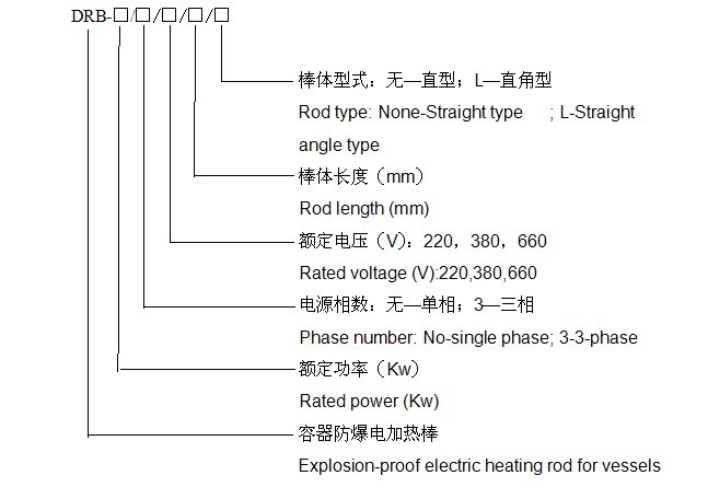
Model meaning
-
Characteristics of electric heating rod
1. The heating rod adopts the mineral insulated (MI) heating cable developed by our company as the heating element.
2. The electric heating rod has a solid structure, high bending strength, small size, airtightness, explosion-proof, and meets the requirements of various types of storage tanks for storing petroleum and its products. Explosion-proof grade dⅡB T1~T6.
3. The heating rod has uniform heat generation, low surface heat load, reliable operation and long service life. There is no reactive power loss, high thermal efficiency, convenient operation and maintenance, and daily maintenance is not required.
4. The electric heating rod has good corrosion resistance to crude oil and its finished products.
Working principle
The electric heating rod uses mineral insulated (MI) heating cables as heating elements. The internal cavity of the rod can quickly conduct heat, fully transfer the electric heat to the rod body and release it to the medium through the external surface of the rod. All electrical energy is converted into heat energy, and the heat transfer efficiency is very high. high.
-
1. Installation of heating rod
Before installing the electric heating rod, check whether the equipment is defective, and use a 1000V shaker to measure the insulation resistance between the conductive part and the shell, the insulation resistance is 1.5~10MΩ, and the 4mm2 or more stranded copper wire must be used for reliable grounding during installation. Ground resistance ≤10Ω.
When electrical wiring, it must be installed in strict accordance with the requirements of electrical explosion-proof regulations, and the joints of the junction box must be coated with industrial petroleum jelly to ensure that the seal is intact. It is strictly forbidden to use the knife switch to control the operation of the electric heating rod.
1.1 Installation of straight electric heating rod
a The arrangement of the electric heating rod in the oil tank is shown in Figure 3 and Figure 4.
b Installation method: DRB type electric heating rod is installed horizontally. First weld the installation nipple on the oil tank (whether there is a reinforced ring plate on the tank wall is determined by the process design, the installation nipple is provided by us, and the specifications are shown in Table 1), and the electric heating rod is passed through the connecting flange on the installation nipple Installed on the tank, an oil-resistant asbestos rubber gasket should be added between the two flanges, and the bolts should be used to fasten it without leakage (see Figure 5). The inlet of the junction box must be installed downwards. A bracket should be added to the rod body in the tank, and the bracket should be prepared by the user (see Figure 6). The highest position of the rod installation must be controlled below the lowest working level of the oil tank process design.
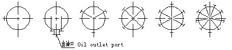
Single stick two sticks three sticks four sticks six sticks nine to eighteen sticks (Uniform perimeter)
Figure 3: Plane layout of straight electric heating rods on vertical oil tanks
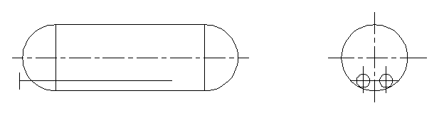
Figure 4: Horizontal installation of straight electric heating rods on horizontal oil tanks (small oil tanks below 60 cubic meters)
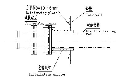
Picture 5: DRB type electric heating rod installation short section
Picture 6: Electric heating rod bracket in the tank
1.2 Installation of right-angle electric heating rod
The right-angle electric heating rod can be inserted from the upper manhole of the oil tank, so that the lower part of the electric heating rod is placed horizontally at the bottom of the oil tank (see Figure 7 and Figure 8). The electric heating rod power cable shall be connected to the electric heating rod junction box by the explosion-proof hose laying method in accordance with the explosion-proof requirements. The contact position between the vertical pipe section and the tank outlet shall be covered with a rubber insulating plate with a thickness of more than 6mm and then fixed firmly to the tank body. Avoid sparks caused by swimming collisions. When installing, remember to make a ground connection wire between the rod and the tank shell.
Solemn warning: Because right-angle rods usually cannot be installed with liquid level controllers, users must formulate operating procedures when draining oil, requiring manual power to be disconnected manually, and the liquid level must be checked before re-powering, if the liquid level is low For heating rods, it is strictly prohibited to switch on and send power (try to control the heating part of the horizontal section to be placed below the oil outlet position).
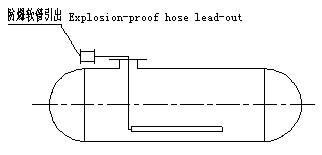
Picture 7: Installation of the right-angle electric heating rod on the horizontal oil tank
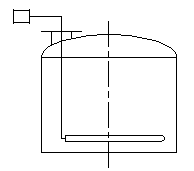
Picture 8: Installation of the right-angle electric heating rod on the vertical oil tank
2. Supporting device installation:
2.1 Control cabinet installation and electrical wiring
Non-explosion-proof electric heating control cabinet should be installed outside the explosion-proof area (safe area). The box body should be vertical when installing, and the grounding wire should be firm and reliable. The floor type requires anchor bolts to fix the box on the foundation.
According to the requirements of explosion-proof regulations, copper core cables are required for power cables and control cables, and their cross-sections should be selected according to the power of the heating rod (the actual cable cross-section should be re-checked by the design according to the voltage drop) and provided by the manufacturer The wiring diagram is correctly wired.
2.2 Installation of temperature measuring resistance:
Because the oil in the tank presents a non-uniform temperature field, the relative position of the temperature measuring resistor and the heating rod should be selected to reflect the true temperature of the oil inside the tank. It is recommended to install it according to the position shown in Figure 9.
Installation method: the temperature measuring resistor is installed in the steel sheathing tube, and the steel sheathing tube is welded to the wall of the oil tank. Use a proper amount of transformer oil, and fasten the positioning screws after inserting the temperature measuring resistor into the steel sheath.
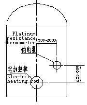
Figure 9: The relative position of the temperature measuring resistor and the heating rod installation
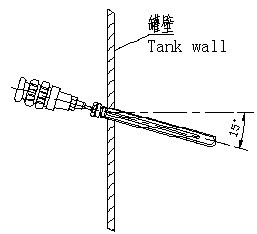
Figure 10: Installation of the temperature measuring resistor on the oil tank
2.3 Installation of float level controller:
The relative position of the float level controller and the electric heating rod (see Figure 11), the installation sub-section is welded horizontally on the tank wall, and the float level controller is installed on the sub-section by flange connection. Flange Asbestos rubber pads are needed between. The installation puppet is provided by the product manufacturer, and the outer diameter is Φ90mm (see Figure 12).
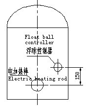
Figure 11: The relative position of the float controller and the heating rod
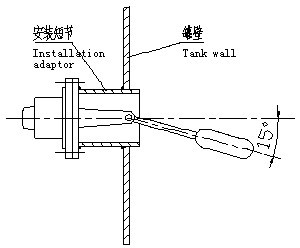
Figure 12: Installation of the float controller on the oil tank
Note: When arranging the relative positions of the electric heating rod, the float level controller, and the temperature measuring resistor, the lowest position of the float should be 150mm higher than the upper surface of the electric heating rod. At the same time, it should be 100mm higher than the bottom end of the platinum thermal resistance.
3. Trial run
Check before trial operation
Check whether the installation positions of the heating rods and supporting components are correct, whether the connecting bolts are loose, the grounding has been done reliably, and whether the grounding resistance is qualified. Check whether the electrical wiring conforms to the drawing, whether the wiring process meets the installation requirements, and whether the bolt connection is firm. Use a 1000V shaker to check whether the live part and the shell are well insulated, and the insulation resistance is ≥1.5MΩ (the insulation resistance of the marine heating rod is ≥10MΩ). Check whether the over-temperature protection sensor is connected. Check whether the oil level in the oil tank is higher than the top of the heating rod. Whether all electrical equipment and wiring requirements comply with explosion-proof regulations (when used in explosion-proof places).
Trial run
Set various process temperature constants according to the temperature regulator manual. Turn the switch to the manual position and then power on. Observe whether the components and circuits in the electric control cabinet work normally and whether there is any abnormality. Measure the voltage and current of each phase of the heating rod, and make a record. After 2 hours of operation in the manual position, the condition is normal, you can turn the switch to the automatic position and put the equipment into automatic operation.


WRITE A MESSAGE TO US
If you are interested in our products, please leave your email, we will contact you as soon as possible, thank you!