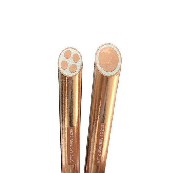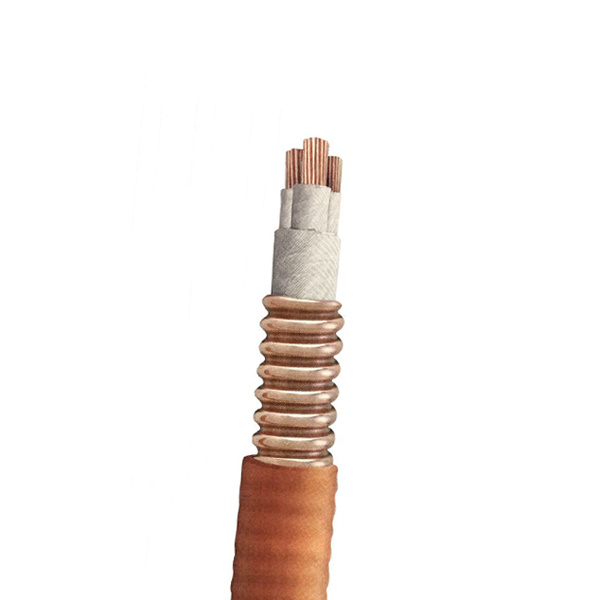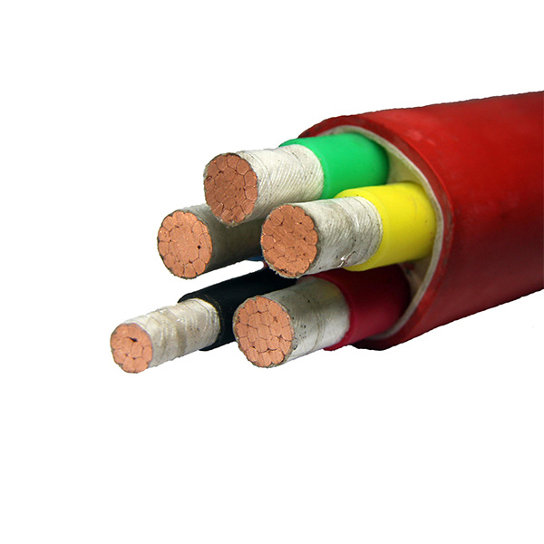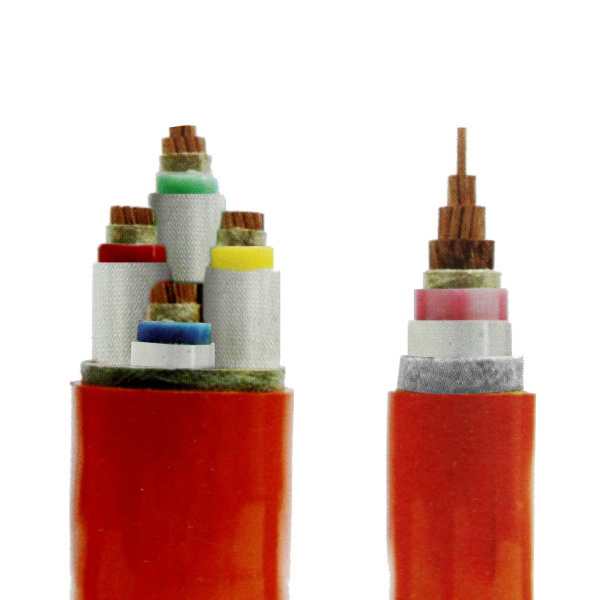
Medium and high voltage cables
Cross-linked polyethylene insulated power cables use chemical or physical methods to transform polyethylene molecules from linear molecular structures to three-dimensional network structures; from thermoplastic polyethylene to thermosetting cross-linked polyethylene, which greatly improves Improved its heat resistance and mechanical properties, and maintained excellent electrical properties. The conductor working temperature of the cross-linked polyethylene insulated power cable is 90°C, and it has the characteristics of simple structure, light weight and chemical resistance, easy to use, and not restricted by the installation drop. The cables are used in power frequency voltage U0/U6/6 (6/10), 8.7/10 (8.7/15), 12/20, 26/35 (26/45) kV power transmission and distribution systems.
Classification:
Key words:
Medium and high voltage cables
- Description
- Model and specification
- Usage characteristics
- Parameter
- Transportation
-
- Commodity name: Medium and high voltage cables
- Commodity ID: 1329827708283801600
Cross-linked polyethylene insulated power cables use chemical or physical methods to transform polyethylene molecules from linear molecular structures to three-dimensional network structures; from thermoplastic polyethylene to thermosetting cross-linked polyethylene, which greatly improves Improved its heat resistance and mechanical properties, and maintained excellent electrical properties. The conductor working temperature of the cross-linked polyethylene insulated power cable is 90°C, and it has the characteristics of simple structure, light weight and chemical resistance, easy to use, and not restricted by the installation drop. The cables are used in power frequency voltage U0/U6/6 (6/10), 8.7/10 (8.7/15), 12/20, 26/35 (26/45) kV power transmission and distribution systems.
Standard
This product is based on GB/T12706.2 "Rated voltage 1kV (Um=1.2kV) to 35kV (Um=40.5kV) extruded insulated power cables and accessories Part 2: Rated voltage 6 kV (Um=7.2kV) and 30kV ( Um=36kV) cable" and GB/T12706.3 "Rated voltage 1kV (Um=1.2kV) to 35kV (Um=40.5kV) extruded insulated power cable and accessories Part 3: Rated voltage 35kV (Um=40.5kV) Cable" production.
Features and uses
Cross-linked polyethylene insulated power cables use chemical or physical methods to transform polyethylene molecules from linear molecular structures to three-dimensional network structures; from thermoplastic polyethylene to thermosetting cross-linked polyethylene, which greatly improves Improved its heat resistance and mechanical properties, and maintained excellent electrical properties.
The conductor working temperature of the cross-linked polyethylene insulated power cable is 90°C, and it has the characteristics of simple structure, light weight and chemical resistance, easy to use, and not restricted by the installation drop.
The cable is used for power frequency voltage U0/U6/6 (6/10), 8.7/10 (8.7/15), 12/20, 26/35 (26/45) kV power transmission and distribution system. -
Model, name and purpose
Model
Name
Scope of application
YJV
YJLV
Z(R)-YJV
Z(R)-YJLV
Copper core or aluminum core XLPE insulated and PVC sheathed power cable
Suitable for indoor and outdoor laying, where it can withstand a certain laying traction, but cannot withstand external mechanical forces. Single-core cables are not allowed to be laid in magnetic pipes
YJV22
YJLV22
Z(R)-YJV22
Z(R)-YJLV22
Copper core or aluminum core XLPE insulated PVC sheathed steel tape armored power cable
Suitable for buried laying, can withstand external mechanical forces, but cannot withstand large pulling forces
Note: Flame-retardant cables meet the burning test requirements of GB/T19666 and GB/T18380 or IEC60332-2. ZC means flame-retardant class C, ZB means flame-retardant class B, and ZA means flame-retardant class A.
Specifications
Model
Number of cores
Rated voltage U0/U (Um) kV
3.6/6
6/6 6/10
8.7/10
8.7/15
12/20
18/30
21/35
26/35
YJV
Z(R)-YJV
1
16-500
25-500
35-500
50-500
YJLV
Z(R)-YJLV
16-500
25-500
35-500
50-500
YJV
Z(R)-YJV
3
16-500
25-500
35-500
50-500
YJLV
Z(R)-YJLV
16-500
25-500
35-500
50-500
YJV22
Z(R)-YJV22
3
16-500
25-500
35-500
50-500
YJLV22
Z(R)-YJLV22
1. 1. U0-The rated voltage between the conductor used in the cable design and the metal shield or sheath;
Rated power frequency voltage between conductors for U-cable design;
Um-The maximum value of the highest system voltage that the device can withstand;
2. 2. U0 is divided into two categories according to the duration of the system ground fault, the specific categories are as follows:
Type 1 cables are used in systems where the single-phase ground fault time is generally not more than 1 mim each time, and can also be used in systems where the longest time is not more than 8h, and the cumulative annual time is not more than 125h.
Category 2 cables-used in systems with longer ground fault times and where higher requirements for cable insulation performance are required, Category 2 should also be adopted.
Typical structure description
1. 1. Conductor
The conductor part is composed of copper or aluminum and is tightly compressed and stranded by a nano-stretching die. It has the characteristics of smooth surface, good roundness, and large compaction coefficient.
2. 2. Semi-conductive shield
The semi-conductive materials of the conductor shielding and insulation shielding are all cross-linked, super smooth, and can adapt to three-layer co-extrusion.
3. 3. Insulation
The 35kV insulation material adopts imported ultra-purified cross-linked polyethylene material, and the purification level of the feeding system in the production process is 1000, which strictly guarantees the purification degree of the raw materials.
4. 4. Metal shield
Copper tape is used to meet the requirements of mechanical properties and short-circuit capacity.
5. 5. Inner sheath and filling
The filling is made of polypropylene tear film and the stranded filling rope, which can prevent the longitudinal penetration of water and increase the service life of the cable.
The inner sheath can be made of PVC plastic according to customer requirements; if the cable has waterproof requirements, the inner lining layer is made of extruded black linear low-density polyethylene.
6. 6. Armour layer
To meet the requirements of withstanding mechanical external forces during installation and laying, galvanized steel strips are used.
7. 7. Outer sheath
According to customer requirements, PVC and PE plastics can be used, and ordinary, flame-retardant, halogen-free and low-smoke, anti-termite, anti-rodent, weather-resistant, etc. can be provided. Its thickness is determined according to the outer diameter before extrusion or the international standard provided. -
1. 6-35kV cable core allows long-term maximum working temperature of 90℃.
2. The core short-circuit temperature shall not exceed 250℃, and the maximum duration shall not exceed 5 seconds.
3. Bending radius
Single core cable allowable bending radius: 20(d+D)±5%
Allowable bending radius of multi-core cable: 15(d+D)±5%
D-The actual outer diameter of the cable sample (mm),
d-The actual diameter of the conductor (mm).
4. Laying is not restricted by the horizontal drop.
5. Laying temperature
When laying below 0℃, it must be heated in advance. -
Cable structure parameters
3.6/6kV flame-retardant and non-flame-retardant single-core XLPE insulated and PVC sheathed power cable
Nominal section mm²
Nominal thickness of insulation mm
Theoretical cable outer diameter mm
Theoretical weight kg/km
Maximum DC resistance of conductor (20℃) Ω/km
YJV YJLV
YJV
YJLV
Cu
AL
1*10
2.5
16.2
362
299
1.83
3.08
1*16
2.5
17.0
433
334
1.15
1.91
1*25
2.5
18.2
544
389
0.727
1.20
1*35
2.5
19.4
667
451
0.524
0.868
1*50
2.5
20.7
834.
524
0.387
0.641
1*70
2.5
22.6
1066
633
0.268
0.443
1*95
2.5
24.2
1330
742
0.193
0.320
1*120
2.5
25.8
1602
859
0.153
0.253
1*150
2.5
27.4
1911
982
0.124
0.206
1*185
2.5
29.2
2279
1134
0.0991
0.164
1*240
2.6
31.6
2838
1353
0.0754
0.125
1*300
2.8
34.4
3472
1615
0.0601
0.100
1*400
3.0
38.4
4516
2040
0.0470
0.0778
1*500
3.2
42.6
5592
2498
0.0366
0.0605
3.6/6kV flame-retardant and non-flame-retardant three-core XLPE insulated and PVC sheathed power cable
Nominal section mm²
Nominal thickness of insulation mm
Theoretical cable outer diameter mm
Theoretical weight kg/km
Maximum DC resistance of conductor (20℃) Ω/km
YJV
YJLV
YJV22
YJLV22
YJV
YJLV
YJV22
YJLV22
Cu
AL
3*10
2.5
31.0
35.4
1077
886
1809
1619
1.83
3.08
3*16
2.5
32.8
37.0
1314
1013
2070
1769
1.15
1.91
3*25
2.5
35.6
39.8
1678
1208
2496
2026
0.727
1.20
3*35
2.5
37.9
42.3
2066
1397
2946
2289
0.524
0.868
3*50
2.5
40.9
45.3
2599
1659
3558
2618
0.387
0.641
3*70
2.5
44.8
49.4
3321
2005
4393
3078
0.268
0.443
3*95
2.5
48.4
53.0
4175
2390
5332
3547
0.193
0.320
3*120
2.5
51.7
56.7
5015
2759
6301
4046
0.153
0.253
3*150
2.5
55.3
60.5
6016
3197
7420
4602
0.124
0.206
3*185
2.5
58.9
64.1
7158
3682
8654
5177
0.0991
0.164
3*240
2.6
64.5
70.0
8983
4473
10650
6140
0.0754
0.125
3*300
2.8
70.5
76.1
11007
5369
12863
7225
0.0601
0.100
3*400
3.0
78.9
86.1
14304
6787
17280
9762
0.0470
0.0778
3*500
3.2
87.0
94.8
17614
8217
18327
11629
0.0366
0.0605
6/6, 6/10kV flame-retardant and non-flame-retardant single-core XLPE insulated and PVC sheathed power cable
Nominal section mm²
Nominal thickness of insulation mm
Theoretical cable outer diameter mm
Theoretical weight kg/km
Maximum DC resistance of conductor (20℃) Ω/km
YJV
YJLV
YJV
YJLV
Cu
AL
1*16
3.4
18.8
494
395
1.15
1.91
1*25
3.4
20.2
618
463
0.727
1.20
1*35
3.4
21.2
735
519
0.524
0.868
1*50
3.4
22.7
917
607
0.387
0.641
1*70
3.4
24.4
1143
710
0.268
0.443
1*95
3.4
26.2
1425
837
0.193
0.320
1*120
3.4
27.6
1688
945
0.153
0.253
1*150
3.4
29.4
2016
1088
0.124
0.206
1*185
3.4
31.0
2375
1230
0.0991
0.164
1*240
3.4
33.4
2946
1460
0.0754
0.125
1*300
3.4
35.8
3563
1706
0.0601
0.100
1*400
3.4
39.2
4570
2094
0.0470
0.0778
1*500
3.4
42.8
5567
2472
0.0366
0.0605
6/6, 6/10kV flame-retardant and non-flame-retardant three-core XLPE insulated and PVC sheathed power cable
Nominal section mm²
Nominal thickness of insulation mm
Theoretical cable outer diameter mm
Theoretical weight kg/km
Maximum DC resistance of conductor (20℃) Ω/km
YJV
YJLV
YJV22
YJLV22
YJV
YJLV
YJV22
YJLV22
Cu
AL
3*16
3.4
36.9
41.3
1537
1236
2403
2103
1.15
1.91
3*25
3.4
39.7
44.3
1917
1447
2869
2399
0.727
1.20
3*35
3.4
42.0
46.4
2308
1650
3292
2634
0.524
0.868
3*50
3.4
45.0
49.8
2868
1928
3968
3029
0.387
0.641
3*70
3.4
48.9
53.9
3612
2296
4831
3515
0.268
0.443
3*95
3.4
52.7
57.5
4509
2724
5794
4009
0.193
0.320
3*120
3.4
55.9
60.9
5369
3113
6760
4504
0.153
0.253
3*150
3.4
59.6
64.6
6392
3573
7872
5053
0.124
0.206
3*185
3.4
63.2
68.4
7557
4080
9159
5682
0.0991
0.164
3*240
3.4
68.2
73.8
9343
4832
11137
6627
0.0754
0.125
3*300
3.4
73.3
79.1
11306
5668
13271
7633
0.0601
0.100
3*400
3.4
80.6
87.8
14500
6983
17540
10023
0.0470
0.0778
3*500
3.4
88.1
95.7
17760
8363
21166
11770
0.0366
0.0605
8.7/10, 8.7/15kV flame-retardant and non-flame-retardant single-core XLPE insulated and PVC sheathed power cable
Nominal section mm²
Nominal thickness of insulation mm
Theoretical cable outer diameter mm
Theoretical weight kg/km
Maximum DC resistance of conductor (20℃) Ω/km
YJV
YJLV
YJV
YJLV
Cu
AL
1*25
4.5
22.6
716
561
0.727
1.20
1*35
4.5
23.6
837
620
0.524
0.868
1*50
4.5
24.9
1012
703
0.387
0.641
1*70
4.5
26.8
1258
825
0.268
0.443
1*95
4.5
28.6
1546
958
0.193
0.320
1*120
4.5
30.0
1815
1072
0.153
0.253
1*150
4.5
31.8
2151
1222
0.124
0.206
1*185
4.5
33.4
2516
1371
0.0991
0.164
1*240
4.5
35.8
3096
1611
0.0754
0.125
1*300
4.5
38.2
3723
1866
0.0601
0.100
1*400
4.5
41.6
4743
2267
0.0470
0.0778
1*500
4.5
45.2
5789
2694
0.0366
0.0605
8.7/10, 8.7/15kV flame-retardant and non-flame-retardant three-core XLPE insulated and PVC sheathed power cable
Nominal section mm²
Nominal thickness of insulation mm
Theoretical cable outer diameter mm
Theoretical weight kg/km
Maximum DC resistance of conductor (20℃) Ω/km
YJV
YJLV
YJV22
YJLV22
YJV
YJLV
YJV22
YJLV22
Cu
AL
3*25
4.5
44.8
49.4
2256
1787
3329
2859
0.727
1.20
3*35
4.5
47.1
51.7
2664
2006
3791
3133
0.524
0.868
3*50
4.5
50.1
54.9
3246
2307
4470
3530
0.387
0.641
3*70
4.5
54.0
58.8
4018
2702
5334
4019
0.268
0.443
3*95
4.5
57.7
62.9
4919
3133
6381
4596
0.193
0.320
3*120
4.5
60.9
66.3
5800
3544
7374
5119
0.153
0.253
3*150
4.5
64.5
69.9
6848
4029
8515
5696
0.124
0.206
3*185
4.5
68.2
73.8
8037
4560
9832
6355
0.0991
0.164
3*240
4.5
73.3
79.1
9888
5378
11853
7343
0.0754
0.125
3*300
4.5
78.4
85.6
12889
6251
14849
9211
0.0601
0.100
3*400
4.5
85.7
93.1
15136
7619
18409
10892
0.0470
0.0778
3*500
4.5
93.2
101.8
18450
9053
22290
12894
0.0366
0.0605
12/20kV flame-retardant and non-flame-retardant single-core XLPE insulated and PVC sheathed power cable
Nominal section mm²
Nominal thickness of insulation mm
Theoretical cable outer diameter mm
Theoretical weight kg/km
Maximum DC resistance of conductor (20℃) Ω/km
YJV
YJLV
YJV
YJLV
铜Cu
铝AL
1*35
5.5
25.8
939
722
0.524
0.868
1*50
5.5
27.3
1132
823
0.387
0.641
1*70
5.5
29.0
1372
939
0.268
0.443
1*95
5.5
30.8
1667
1079
0.193
0.320
1*120
5.5
32.4
1957
1214
0.153
0.253
1*150
5.5
34.0
2283
1355
0.124
0.206
1*185
5.5
35.8
2671
1526
0.0991
0.164
1*240
5.5
38.2
3262
1776
0.0754
0.125
1*300
5.5
40.4
3879
2022
0.0601
0.100
1*400
5.5
43.8
4912
2436
0.0470
0.0778
1*500
5.5
47.4
5971
2876
0.0366
0.0605
12/20kV flame-retardant and non-flame-retardant three-core XLPE insulated and PVC sheathed power cable
Nominal section mm²
Nominal thickness of insulation mm
Theoretical cable outer diameter mm
Theoretical weight kg/km
Maximum DC resistance of conductor (20℃) Ω/km
YJV
YJLV
YJV22
YJLV22
YJV
YJLV
YJV22
YJLV22
Cu
AL
3*35
5.5
51.9
57.1
3026
2368
4343
3686
0.524
0.868
3*50
5.5
54.9
60.1
3628
2688
5020
4080
0.387
0.641
3*70
5.5
58.7
64.1
4425
3110
5944
4629
0.268
0.443
3*95
5.5
62.6
68.2
5377
3592
7025
5240
0.193
0.320
3*120
5.5
65.8
71.4
6281
4026
8012
5757
0.153
0.253
3*150
5.5
69.4
75.0
7355
4536
9181
6362
0.124
0.206
3*185
5.5
73.1
79.3
8570
5093
10602
7125
0.0991
0.164
3*240
5.5
78.2
84.4
10458
5948
12631
8121
0.0754
0.125
3*300
5.5
83.1
90.9
12459
6822
15721
10083
0.0601
0.100
3*400
5.5
90.6
98.6
15794
8277
19388
11871
0.0470
0.0778
3*500
5.5
98.1
106.5
19162
9765
23147
13575
0.0366
0.0605
18/30kV flame-retardant and non-flame-retardant single-core XLPE insulated and PVC sheathed power cable
Nominal section mm²
Nominal thickness of insulation mm
Theoretical cable outer diameter mm
Theoretical weight kg/km
Maximum DC resistance of conductor (20℃) Ω/km
YJV
YJLV
YJV
YJLV
Cu
AL
1*50
8.0
34.5
1552
1242
0.387
0.641
1*70
8.0
36.2
1812
1379
0.268
0.443
1*95
8.0
38.0
2130
1542
0.193
0.320
1*120
8.0
39.4
2420
1678
0.153
0.253
1*150
8.0
41.2
2785
1857
0.124
0.206
1*185
8.0
42.8
3175
2030
0.0991
0.164
1*240
8.0
45.2
3795
2309
0.0754
0.125
1*300
8.0
47.6
4461
2604
0.0601
0.100
1*400
8.0
51.0
5535
3059
0.0470
0.0778
1*500
8.0
54.6
6639
3544
0.0366
0.0605
21/35kV flame-retardant and non-flame-retardant single-core XLPE insulated and PVC sheathed power cable
Nominal section mm²
Nominal thickness of insulation mm
Theoretical cable outer diameter mm
Theoretical weight kg/km
Maximum DC resistance of conductor (20℃)Ω/km
YJV
YJLV
YJV
YJLV
Cu
AL
1*50
9.3
37.1
1718
1408
0.387
0.641
1*70
9.3
38.8
1985
1551
0.268
0.443
1*95
9.3
40.6
2310
1722
0.193
0.320
1*120
9.3
42.0
2606
1864
0.153
0.253
1*150
9.3
43.8
2979
2050
0.124
0.206
1*185
9.3
45.4
3375
2230
0.0991
0.164
1*240
9.3
47.8
4005
2519
0.0754
0.125
1*300
9.3
50.2
4681
2824
0.0601
0.100
1*400
9.3
53.6
5769
3293
0.0470
0.0778
1*500
9.3
57.2
6889
3794
0.0366
0.0605
26/35kV flame-retardant and non-flame-retardant single-core XLPE insulated and PVC sheathed power cable
Nominal section mm²
Nominal thickness of insulation mm
Theoretical cable outer diameter mm
Theoretical weight kg/km
Maximum DC resistance of conductor (20℃) Ω/km
YJV
YJLV
YJV
YJLV
Cu
AL
1*50
10.5
39.7
1900
1590
0.387
0.641
1*70
10.5
41.4
2174
1740
0.268
0.443
1*95
10.5
43.2
2507
1919
0.193
0.320
1*120
10.5
44.6
2809
2067
0.153
0.253
1*150
10.5
46.4
3190
2261
0.124
0.206
1*185
10.5
48.0
3593
2448
0.0991
0.164
1*240
10.5
50.4
4233
2747
0.0754
0.125
1*300
10.5
52.8
4919
3062
0.0601
0.100
1*400
10.5
56.2
6022
3546
0.0470
0.0778
1*500
10.5
59.8
7158
4063
0.0366
0.0605
-
Delivery length
The delivery length of the cable should not be less than 100m, and the measurement error should not be greater than ±0.5%.
24 cores and below: It is allowed to deliver short cables with a length of not less than 20 meters, and the quantity should not exceed 5% of the total length of delivery.
More than 24 cores: It is allowed to deliver short cables with a length of not less than 20 meters, and the quantity should not exceed 10% of the total length of delivery.
According to the agreement between the two parties, any length of cable is allowed to be delivered.
Packaging signs and transportation
Cables in coils or coils should be neatly wound and properly packaged.
Each circle or plate should be attached with a label indicating:
Manufacturer name or trademark
Cable model and specification mm2
Rated voltage V
Length m
Manufacturing Date: Year Month
Standard number
Gross weight kg:
Correct rotation direction of the cable reel
Transport and storage
Spools are not allowed to lay flat
During transportation, it is strictly forbidden to lower the cable reel with cables from a high place, and it is strictly forbidden to lose the cables mechanically.
When hoisting packages, it is strictly forbidden to hoist several trays at the same time. On vehicles, ships and other transportation tools, the cable reel must be placed firmly and fixed with a suitable method to prevent mutual collision or overturning.
Previous
Next
WRITE A MESSAGE TO US
If you are interested in our products, please leave your email, we will contact you as soon as possible, thank you!


