


Heating Cable
It is composed of a heating conductor, an insulating layer of tightly compacted mineral powder (usually magnesium oxide powder) and a metal sheath. For copper sheathed heating cables, a layer of high-density polyethylene (HDPE) or flame-retardant HDPE plastic jacket can be extruded on the outer circumference of the metal sheath according to the needs of anti-corrosion and anti-mechanical damage in the place of use. Commonly used structures are single-core and two-core, and can also be designed and provided with three-core and above mineral insulated heating cables according to your needs. The sheath materials include copper, cupronickel, austenitic stainless steel (304L, 321, 316L, 347, etc.), inconel and 825 high temperature corrosion resistant alloy, etc., which should be selected according to different operating temperatures and corrosive environments.
Classification:
Key words:
Heating Cable
- Description
- Product characteristics
- Product code
- Parameter
- Design and selection
- Laying and installation
- Application Area
-
- Commodity name: Heating Cable
It is composed of a heating conductor, an insulating layer of tightly compacted mineral powder (usually magnesium oxide powder) and a metal sheath. For copper sheathed heating cables, a layer of high-density polyethylene (HDPE) or flame-retardant HDPE plastic jacket can be extruded on the outer circumference of the metal sheath according to the needs of anti-corrosion and anti-mechanical damage in the place of use. Commonly used structures are single-core and two-core, and can also be designed and provided with three-core and above mineral insulated heating cables according to your needs. The sheath materials include copper, cupronickel, austenitic stainless steel (304L, 321, 316L, 347, etc.), inconel and 825 high temperature corrosion resistant alloy, etc., which should be selected according to different operating temperatures and corrosive environments.
Product structure
Mineral Insulated Heating Cable
It is composed of a heating conductor, an insulating layer of tightly compacted mineral powder (usually magnesium oxide powder) and a metal sheath. For copper sheathed heating cables, a layer of high-density polyethylene (HDPE) or flame-retardant HDPE plastic jacket can be extruded on the outer circumference of the metal sheath according to the needs of anti-corrosion and anti-mechanical damage in the place of use.
The common structure is single-core and two-core, and three-core and above mineral insulated heating cables can also be designed and provided according to your needs.
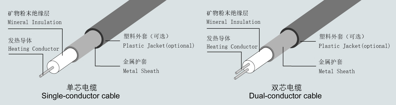
Sheath materials include copper, cupronickel, austenitic stainless steel (304L, 321, 316L, 347, etc.), inconel and 825 high temperature corrosion resistant alloy, etc., which should be carried out according to different operating temperatures and corrosive environments Optional.
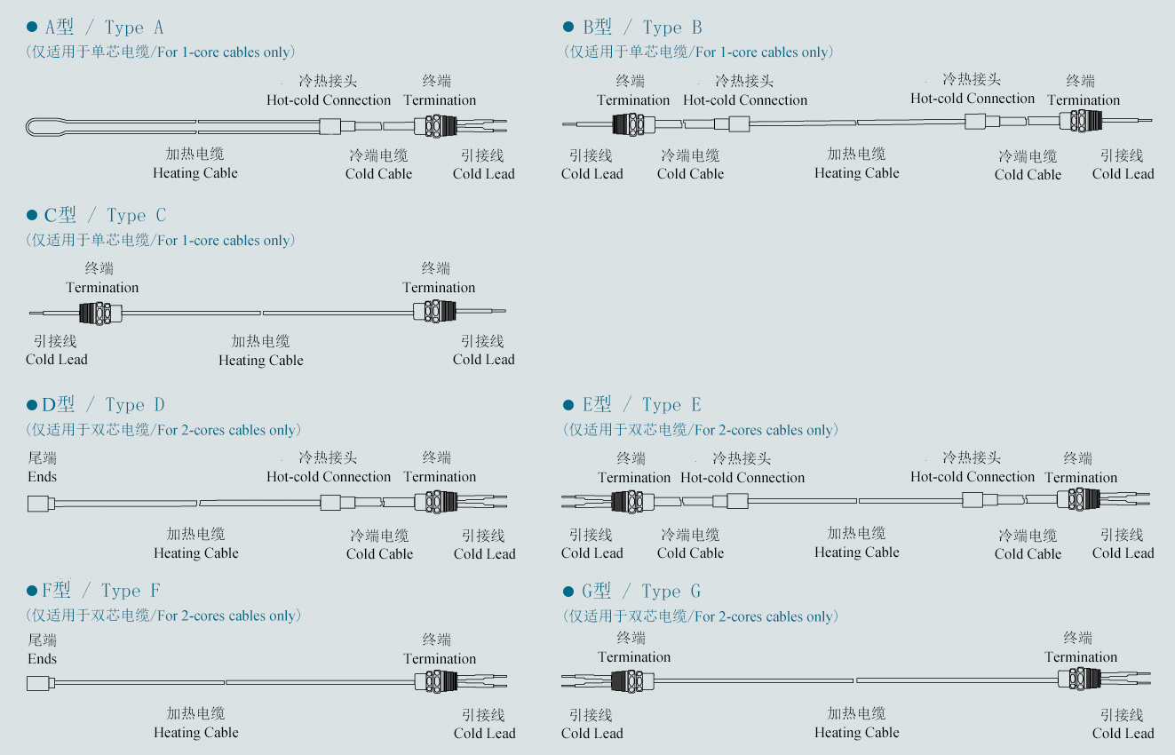
Mineral Insulated Heating Unit (Mineral Insulated Heating Unit)
This product is based on the design and selection of mineral insulated heating cables, and is prefabricated in the manufacturer's factory for heating unit devices that can be directly connected to the power supply. It is usually composed of heating cables, hot and cold joints, cold end cables, terminals, tail ends, and lead wires. There are types A, B, C, D, E, F, and G. Types A, B, and C are only suitable for single-core heating cables, and types D, E, F, and G are only suitable for double-core heating cables.
-
High mechanical strength
The high-strength metal tube is used as the sheath, which forms a compact body with the conductor and mineral insulating powder during the processing. The structure is firm, the mechanical strength is high, and it is resistant to mechanical extrusion and bending.
Stable physical and chemical properties
The constituent materials are all inorganic materials with good thermal stability. When used under the rated temperature and set environment, the structure, electrical conductivity, dielectric strength, chemical composition and other mechanical, physical and chemical properties are quite stable.
Small temperature difference between inside and outside
The thermal resistance coefficient of magnesium oxide insulation is 3-5 times lower than that of most organic insulating materials. The small thermal resistance can make the heat transfer from the inner conductor to the metal sheath sharply, so the temperature difference between the conductor and the surface of the sheath is very small, which allows a larger current density.
High electric and heat conversion efficiency
Using the principle of the thermal effect of electric current (Joule-Lenz's law), pure resistance heats up, almost 100% of the electrical energy is converted into heat.
Electrical control is convenient
The working voltage is 50-60HZ power frequency, and the ON/OFF or PID temperature control is selected according to actual needs. The technology is mature, the operation is reliable, and the maintenance is small.
Corrosion resistance
According to the temperature of the environment and the corrosive medium, the appropriate metal sheath material can be selected to achieve the best corrosion resistance.
Radiation resistance
The inorganic materials used have good radiation resistance. The literature shows that when this type of cable runs at 200℃-700℃ and the neutron flux is 1021 neutrons/cm2, its technical performance actually does not occur. Changes can be applied to the core radiation area of nuclear power plants.
Explosion-proof certificate
The company's mineral insulated heating cable products have obtained the IEC Ex and ATEX explosion-proof certificates issued by the British CML.


Product name
IEC Ex certificate number
ATEX certificate number
Explosion-proof grade
Protection
Level
MICU & MIHC
Mineral insulated heating cable
IECEx CML 16.0075
CML 16ATEX3164
Ex e IIC T1 ~ T6 Gb
Ex tb IIIC T450℃~T85℃ Db
IP67
MICN
Mineral insulated heating cable
IECEx CML 16.0079
CML 16ATEX3169
Ex e IIC T1 ~ T6 Gb
Ex tb IIIC T450℃~T85℃ Db
IP67
MISS
Mineral insulated heating cable
IECEx CML 16.0080
CML 16ATEX3170
Ex e IIC T1 ~ T6 Gb
Ex tb IIIC T450℃~T85℃ Db
IP67
MIAL
Mineral insulated heating cable
IECEx CML 16.0081
CML 16ATEX3171
Ex e IIC T1 ~ T6 Gb
Ex tb IIIC T450℃~T85℃ Db
IP67
-
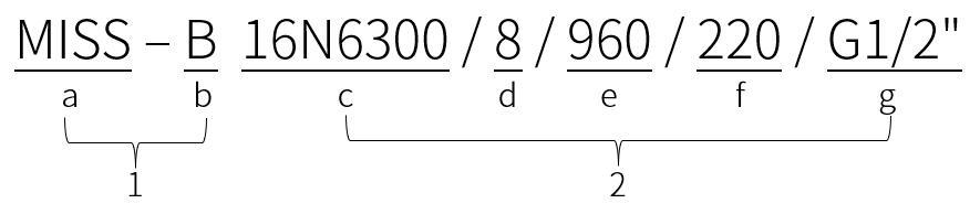
Mineral insulated heating cable
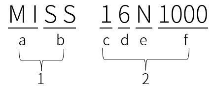
Code description:
Serial number
Name
Code
Code name
Interpretation meaning
1
Model
a
Product name
MI: Mineral insulated heating cable
b
Sheath material
CU: Copper sheath
HC: Copper sheath + HDPE jacket
HF: Copper sheath + flame-retardant HDPE jacket
SS: Stainless steel sheath
AL: 825 alloy sheath
2
Specifications
c
Number of conductor cores
1: Single core (1 core)
2: Double core (2 core)
d
Voltage rating
3: 300V
6: 600V
e
Heating conductor material
T: Copper
K: Copper-nickel alloy
N: nickel-chromium alloy
f
Unit conductor resistance
At 20℃, the nominal value of conductor resistance with a length of 1km (Ω/km)
Mineral insulated cold end cable
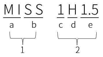
Code description:
Serial number
Name
Code
Code name
Interpretation meaning
1
Model
a
Product name
MI: Mineral insulated cold end cable
b
Sheath material
HC: Copper sheath + HDPE jacket
HF: Copper sheath + flame-retardant HDPE jacket
SS: Stainless steel sheath
AL: 825 alloy sheath
2
Specifications
c
Number of conductor cores
1: Single core (1 core)
2: Double core (2 core)
d
Voltage rating
L: 500V
H: 750V
e
Conductor cross section
Nominal cross-sectional area of conductor (mm2)
Note: The model specifications of the bare copper sheathed mineral insulated cold-end cable can also be expressed in accordance with the method specified in GB/T 13033.1.
Mineral insulation heating element
Code description:
Serial number
Name
Code
Code name
Interpretation meaning
1
Model
a
Heating cable model
Design optional mineral insulated heating cable model
b
Component structure style
Designed component structure types: A, B, C, D, E, F, G type
2
Specifications
c
Heating cable specifications
Design and match mineral insulated heating cable specifications
d
Heating cable length
Design and matching mineral insulated heating cable length (m)
e
Design power
Component design power (W)
f
Rated voltage
Component rated working voltage (V)
g
Interface specifications
Installation thread specification of component terminal: M, G or NPT standard thread
-
300VCopper sheathed heating cable (model:MICU)
Specification code
Outer diameter
Nominal resistance of conductor at 20℃
Maximum manufacturing length
Unit weight
mm
Ω/km
m
Kg/km
23C3.4
12.4
3.4
200
698
23C4.4
11.3
4.4
220
571
23C5.8
10.4
5.8
240
476
23C8.6
9.0
8.6
260
351
23C11.4
8.4
11.4
280
299
23C13.8
8.0
13.8
300
268
23C17.2
7.6
17.2
320
239
23C23
7.1
23
340
205
23C34.4
6.6
34.4
360
174
23C49.2
6.2
49.2
380
151
23K160
10.4
160
220
477
23K240
9.0
240
240
351
23K320
8.4
320
265
299
23K384
8.0
384
280
268
23K480
7.7
480
300
244
23K640
7.1
640
320
205
23K960
6.5
960
350
169
Note: The nominal resistance of the double-core cable conductor is the resistance of the double-core loop per 1km, that is, twice the resistance of a single conductor.
300VWhite copper sheathed heating cable (model:MICN)
Specification code
Outer diameter
Nominal resistance of conductor at 20℃
Maximum manufacturing length
Unit weight
mm
Ω/km
m
Kg/km
23K160
10.4
160
202
477
23K240
9.0
240
267
351
23K300
8.4
300
292
302
23K380
8.0
380
320
269
23K480
7.7
480
352
244
23K620
7.1
620
433
206
23K960
6.5
960
458
169
23K1480
6.0
1480
390
141
23K1890
5.7
1890
433
126
23K2340
5.5
2340
471
117
23K3100
5.3
3100
500
107
23K4800
4.9
4800
547
92
Note: The nominal resistance of the double-core cable conductor is the resistance of the double-core loop per 1km, that is, twice the resistance of a single conductor.
300VStainless steel/825Alloy sheathed heating cable (model:MISS/MIAL)
Specification code
Outer diameter
Nominal resistance of conductor at 20℃
Maximum manufacturing length
Unit weight
mm
Ω/km
m
Kg/km
23C34
5.6
34
190
122
23K164
5.0
164
240
95
23K180
6.5
180
140
169
23K210
5.4
210
210
113
23K230
4.8
230
261
86
23K300
5.0
300
240
96
23K328
4.5
328
297
78
23K400
4.8
400
261
87
23K480
4.8
480
261
86
23K650
4.6
650
284
78
23K984
4.8
984
261
86
23K1000
4.1
1000
358
61
23K1300
3.8
1300
417
52
23K1600
4.3
1600
325
68
23K1968
4.8
1968
261
87
23K2000
5.0
2000
241
93
23K2297
4.5
2297
297
76
23K2400
4.8
2400
261
86
23K3000
4.6
3000
284
78
23K4593
4.0
4593
375
58
23N4600
4.8
4600
261
86
23N5577
4.0
5577
375
60
23N7500
4.6
7500
284
77
23N8200
4.0
8200
375
59
23N11200
4.4
11200
311
70
23N14000
4.2
14000
341
63
23N16400
3.5
16400
495
44
23N18000
3.8
18000
420
52
23N19685
3.5
19685
495
44
23N24600
3.0
24600
670
33
23N26000
3.6
26000
464
46
23N29500
3.0
29500
670
32
23N36000
3.4
36000
520
41
23N40000
3.4
40000
520
41
23N50000
3.6
50000
464
41
23N60000
3.6
60000
464
41
23N72000
3.4
72000
520
40
Note: The nominal resistance of the double-core cable conductor is the resistance of the double-core loop per 1km, that is, twice the resistance of a single conductor.
600VCopper sheathed heating cable (model:MICU)
Specification code
Outer diameter
Nominal resistance of conductor at 20℃
Maximum manufacturing length
Unit weight
mm
Ω/km
m
Kg/km
16C0.7
9.6
0.7
340
497
16C0.9
9.1
0.9
340
427
16C1.0
8.7
1.0
350
390
16C1.3
8.0
1.3
350
321
16C1.7
7.3
1.7
350
261
16C2.2
7.0
2.2
380
232
16C2.9
6.4
2.9
400
190
16C4
5.9
4
600
156
16C7
5.3
7
600
119
16C11
4.9
11
600
99
16C13
4.6
13
600
87
16C17
4.6
17
600
85
16C21
4.6
21
600
84
16C25
3.7
25
600
55
16C33
4.6
33
600
82
16C40
3.4
40
600
45
16C63
3.2
63
600
39
16K66
5.2
66
384
114
16K80
5.3
80
370
120
16K100
5.2
100
450
112
16K131
4.9
131
600
99
16K140
4.9
140
600
98
16K197
4.45
197
600
79
16K220
4.5
220
600
81
16K262
4.3
262
600
73
16K315
4.3
315
600
78
16K345
4.2
345
600
74
16K450
4.0
450
600
66
16K492
4.0
492
600
65
16K630
4.0
630
600
64
16K800
3.5
800
600
49
16K984
4.0
984
600
62
16K1280
3.7
1280
600
53
16K2000
3.6
2000
600
49
16K3000
3.6
3000
600
49
26C3.4
12.9
3.4
150
745
26C4.4
12.2
4.4
160
650
26C5.8
11.3
5.8
170
547
26C8.6
9.9
8.6
180
413
26C11.4
9.3
11.4
200
357
26C13.8
9.0
13.8
210
332
26C17.2
8.6
17.2
220
299
26C23
8.0
23
250
255
26C34.4
7.5
34.4
280
220
26C49.2
7.1
49.2
300
195
26K240
9.9
240
180
413
26K320
9.3
320
200
357
26K384
9.0
384
210
332
26K480
8.6
480
220
299
26K640
8.0
640
250
255
26K960
7.5
960
280
220
Note: The nominal resistance of the double-core cable conductor is the resistance of the double-core loop per 1km, that is, twice the resistance of a single conductor.
600VWhite copper sheathed heating cable (model:MICN)
Specification code
Outer diameter
Nominal resistance of conductor at 20℃
Maximum manufacturing length
Unit weight
mm
Ω/km
m
Kg/km
16C3
6.4
3
255
188
16C4
5.9
4
300
156
16C5
5.7
5
320
142
16C6
5.5
6
345
130
16C7
5.3
7
350
119
16C8
5.2
8
362
113
16C9
5.1
9
376
108
16C11
4.9
11
400
99
16C17
4.6
17
500
85
16C25
3.7
25
600
55
16C40
3.4
40
600
45
16C63
3.2
63
300
39
16K82
5.7
82
350
165
16C93
3.2
93
300
39
16K122
5.2
122
400
125
16K160
4.9
160
500
108
16K188
4.7
188
600
98
16K250
4.4
250
600
84
16K312
4.2
312
600
75
16K400
4.0
400
600
67
16K478
3.8
478
600
60
16K630
3.7
630
600
55
16K1000
3.4
1000
600
46
16K1600
3.2
1600
600
40
16K2210
3.2
2210
300
39
16K2400
3.1
2400
600
37
16K4150
3.0
4150
600
34
26K160
11.2
160
184
539
26K240
9.9
240
226
413
26K300
9.3
300
246
360
26K380
9.0
380
273
332
26K480
8.6
480
292
299
26K620
8.0
620
327
256
26K960
7.5
960
352
220
26K1480
7.1
1480
305
194
26K1600
6.0
1600
405
141
26K1890
6.8
1890
335
178
26K2340
6.4
2340
361
157
26K3100
6.2
3100
380
146
26K4800
5.8
4800
422
127
Note: The nominal resistance of the double-core cable conductor is the resistance of the double-core loop per 1km, that is, twice the resistance of a single conductor.
600Stainless steel/825Alloy copper sheathed heating cable (model:MISS/MIAL )
Specification code
Outer diameter
Nominal resistance of conductor at 20℃
Maximum manufacturing length
Unit weight
mm
Ω/km
m
Kg/km
16C2.1
6.8
2.1
130
214
16C2.8
6.0
2.8
165
165
16C3.4
5.9
3.4
170
153
16C3.6
6.1
3.6
160
160
16C5.3
5.3
5.3
210
118
16C8
4.7
8
150
91
16C8.5
4.7
8.5
150
90
16C13
4.3
13
190
73
16C21
4.0
21
220
61
16K40
5.8
40
180
149
16K50
5.4
50
210
127
16K60
5.2
60
220
115
16K80
4.8
80
200
96
16K100
4.7
100
160
90
16K120
4.5
120
170
81
16K131
4.0
131
215
63
16K153
4.2
153
195
70
16N160
6.5
160
150
188
16N200
5.9
200
180
154
16N250
5.3
250
220
124
16K328
4.0
328
215
60
16N400
4.7
400
280
93
16N500
4.5
500
300
84
16N630
4.3
630
200
75
16N900
3.9
900
230
60
16N1000
3.9
1000
230
59
16N1250
3.8
1250
210
55
16N1600
3.6
1600
270
49
16N2400
3.2
2400
350
38
16N2500
3.4
2500
300
43
16N2800
3.4
2800
300
42
16N3300
3.4
3300
300
42
16N4000
3.2
4000
350
37
16N5200
3.2
5200
350
37
16N6300
3.2
6300
350
36
16N10000
3.2
10000
350
36
16N20000
3.2
20000
350
36
26C8.4
9.8
8.4
60
386
26C13.4
8.7
13.4
80
296
26C21
7.9
21
95
238
26C34
7.3
34
110
198
26C54
6.3
54
150
146
26C85
5.6
85
190
114
26C130
5.3
130
215
101
26K180
7.9
180
95
245
26K260
7.4
260
110
210
26K360
6.8
360
130
175
26K500
6.4
500
147
153
26K650
5.9
650
173
129
26K1000
5.7
1000
185
118
26K1300
6.2
1300
156
143
26K2000
5.8
2000
179
123
26K3300
5.4
3300
206
105
26N4600
5.8
4600
179
123
26N8000
5.4
8000
206
105
26N13000
5.0
13000
241
89
26N27000
4.8
27000
261
81
26N40000
4.6
40000
284
74
26N60000
4.4
60000
311
68
26N72000
4.2
72000
341
62
Note: The nominal resistance of the double-core cable conductor is the resistance of the double-core loop per 1km, that is, twice the resistance of a single conductor.
Mineral insulated cold end cable specification table
Voltage level
Specifications
Number of conductor cores
Nominal cross section
(mm2)
Nominal outer diameter
(mm)
Conductor resistance at 20℃
Maximum (Ω/km)
Current carrying capacity
(A)
500V
2L1.5
2
1.5
5.7
12.1
20
750V
1H1.5
1
1.5
4.9
12.1
25
1H2.5
1
2.5
5.3
7.41
34
1H4
1
4
5.9
4.61
46
1H6
1
6
6.4
3.08
57
1H10
1
10
7.3
1.83
77
1H16
1
16
8.3
1.15
108
2H1.5
2
1.5
7.9
12.1
25
2H2.5
2
2.5
8.7
7.41
34
2H4
2
4
9.8
4.61
46
-
Applicable standards and norms
General
GB 50264 Code for Design of Industrial Equipment and Pipeline Thermal Insulation Engineering
GB/T 4272 General Rules for Equipment and Pipeline Insulation Technology
GB/T 8175 Design Guidelines for Equipment and Piping Insulation
JGJ 142 Ground Radiant Heating Technical Regulations
HG/T 20514 instrument and pipeline heat tracing and insulation design specification
SH/T 3126 Design Specification for Heat Tracing and Insulation of Petrochemical Instruments and Pipelines
Non-explosive environment
GB/T 32348.2 / IEC 62395-2 Industrial and Commercial Resistive Heating System Part 2: System Design, Installation and Maintenance Application Guide
IEEE Std 515 IEEE Standard for the Testing, Design, Installation, and Maintenance of Electrical Resistance Trace Heating for Industrial Applications
IEEE Std 515.1 IEEE Standard for the Testing, Design, Installation, and Maintenance of Electrical Resistance Trace Heating for Commercial Applications
Explosive environment
GB 3836.1 Explosive Atmosphere Part 1: Equipment General Requirements
GB/T 19518.2 Explosive Atmosphere Resistance Heat Tracing Part 2: Guidelines for Design, Installation and Maintenance
IEC 60079-0 Explosive atmospheres-Part 0: Equipment-General requirements
IEC 60079-30-2 Explosive atmospheres-Part 30-2: Electrical resistance trace heating-Application guide for design, installation and maintenance
Design requirements
1. Before the design of the heating system, adequate technical communication and exchange should be carried out to determine the project requirements, location and use environment. The information to be provided includes at least:
a) Project name, location, purpose and requirements of use;
b) Potential explosion hazard in the place of use (if it is an explosive environment, the explosion-proof grade and temperature group should be clarified);
c) A list of pipes, containers and accessories, including materials, specifications, dimensions, quantities and other information;
d) The composition, properties, quantity or flow rate of the medium in the pipeline or container;
e) Process pipeline diagram;
f) Corrosive media that may exist in the surrounding environment;
g) The highest temperature, lowest temperature and annual average wind speed of the place of use;
h) Insulation structure, material and thickness (if selected by the user), etc.
2. When designing and selecting the heating system, consider the most unfavorable conditions it may use and adapt to these unfavorable conditions. The worst cases include:
a) The maximum ambient temperature, usually 40℃, unless otherwise specified;
b) No wind (still air);
c) Use the minimum thermal conductivity of thermal insulation materials;
d) The design does not use temperature control or simulates temperature controller failure;
e) The heat tracing device operates under the rated voltage plus 10% of the voltage;
f) The conductor resistance value of the heater is the lower limit of the manufacturing tolerance.
3. If it is used under special conditions or the site conditions may be particularly harsh, these conditions should be stated in the engineering technical conditions.
4. Before calculating the electric heating power, first confirm the following purposes of electric heating:
a) Heat tracing: compensate the heat loss under the lowest ambient temperature condition to maintain the specified temperature of the workpiece;
b) Heating: Raise the temperature of the workpiece and its internal substances to the specified value within the specified time;
c) Heating and tracing.
5. The appropriate safety factor should be considered when calculating the electric heating power. The safety factor should be based on past experience, and its range is generally 1.1~1.25, usually 1.2. The following factors should be considered when selecting the safety factor:
a) Deterioration of thermal insulation performance;
b) Changes in power supply voltage;
c) The voltage drop of the power line;
d) Increased radiation and convection heat dissipation in high temperature applications;
e) Installation quality of insulation engineering.
6. When heating and tracing are required, the electric heating power shall be the larger value of the heating power and the heating power calculation result.
7. The heat loss of flanges, valves, brackets, pumps and other pipeline accessories can be converted into equivalent pipeline length for calculation. The converted length of heat loss of typical pipe accessories is as follows:
Nominal diameter
Valve type
Thread
Flange
Orifice plate
Flange
Pipeline
Support
Check valve
Pump
inch
mm
Spinning or welding
Flange connection
Butterfly valve
½
15
0.15
0.31
0
0.15
0.45
0.50
0.10
0.60
¾
20
0.23
0.46
0
0.15
0.45
0.50
0.18
0.90
1
25
0.31
0.61
0.31
0.15
0.45
0.50
0.26
1.20
1¼
32
0.46
0.61
0.31
0.18
0.50
0.50
0.31
1.20
1½
40
0.46
0.72
0.46
0.18
0.50
0.50
0.41
1.20
2
50
0.61
0.76
0.61
0.18
0.50
0.40
0.56
1.50
2½
65
0.69
0.91
0.69
0.18
0.50
0.40
0.64
1.80
3
80
0.76
1.07
0.76
0.18
0.50
0.40
0.71
2.00
4
100
1.22
1.52
0.91
0.25
0.65
0.40
1.02
3.00
5
125
1.52
1.83
0.91
0.25
0.65
0.40
1.32
4.00
6
150
2.13
2.44
1.07
0.25
0.65
0.30
1.93
4.50
8
200
2.90
3.35
1.22
0.28
0.68
0.30
2.70
6.50
10
250
3.81
4.27
1.22
0.28
0.68
0.20
3.51
8.50
12
300
4.57
5.03
1.52
0.41
0.81
0.20
4.02
10.00
14
350
5.49
5.94
1.68
0.43
0.98
0.15
4.94
11.50
16
400
6.55
7.01
1.83
0.55
1.10
0.10
5.05
14.00
18
450
7.77
8.23
1.98
0.55
1.10
-
6.27
16.50
20
500
8.69
9.14
2.13
0.68
1.33
-
7.19
18.50
24
600
10.36
10.87
2.44
0.81
1.51
-
8.76
22.00
30
750
12.19
12.80
3.05
0.98
1.68
-
10.89
25.50
36
900
14.02
14.63
3.66
1.36
1.96
-
12.52
30.00
Note: 1. The converted length of the pipe accessories in the table is the length of the pipe of the corresponding specification when calculating the heat loss.
2. The nominal pressure of the valves listed in the table is 2.0MPa and below.
8. When used in an explosive environment, even if the most unfavourable conditions are considered, the final installation power and the use, installation and operation of electric heating should not cause the explosion of the explosive mixture.
9. Each electric heating circuit should be equipped with over-voltage, overload, short-circuit, leakage and over-temperature protection, and the leakage current is usually set to 30mA.
Selection requirements
1. The following factors should be considered when selecting mineral insulated heating cables and components, and the installation and operation requirements under these factors should be met:
a) The tracing/heating temperature of the workpiece to be heated, the highest temperature the workpiece can withstand and the highest possible temperature;
b) The lowest ambient temperature of the place of use;
c) The corrosive substances and their concentrations that may exist in the place of use;
d) Pipeline heating/heating length or workpiece area, electric heating design calculation power;
e) Mechanical damage that may exist during installation and operation;
f) The installation space around the heated workpiece is limited;
g) The hazard of the place of use, the required explosion-proof grade and temperature group.
2. The sheath material should be selected according to the heat tracing/heating temperature of the workpiece, the highest possible temperature of the workpiece, and the corrosive medium that may exist in the place of use. The maximum sheath temperature allowed for various sheath materials is as follows:
Sheath material
Maximum sheath temperature allowed to be used, ℃
Bare copper
250
Copper+HPDE
90
White copper
400
300 series austenitic stainless steel
600
825 alloy
800
3. The heating element installation method can be parallel laying, spiral winding laying, or meandering (or W-shaped) laying. Parallel installation is preferred.
4. The specification of the heating cable should be based on the theoretical calculation result of the cold resistance of the heating conductor, and the closest specification whose nominal resistance is not greater than the calculation result should be selected from the heating cable specification table of the corresponding sheath material for preliminary selection. After the initial selection, the heating cable should be checked for operating parameters. If it does not meet the requirements, the heating cable specifications should be reselected and checked until the requirements are met. The verification content of the operating parameters of the heating cable includes:
a) The surface load or maximum sheath temperature of the heating cable;
b) Check the current density of the heating conductor.
5. The maximum heating temperature allowed by the heating element is as follows:
Power density
W/cm2
Maximum heat tracing temperature allowed for workpiece, ℃
HDPE outer sheath
Copper sheath
White copper sheath
Stainless steel sheath
825 alloy sheath
0.05
63
205
345
530
715
0.10
34
190
330
520
705
0.20
-
160
312
510
695
0.30
-
132
297
500
685
0.40
-
103
275
492
676
0.50
-
75
257
485
670
0.60
-
45
235
480
665
0.70
-
-
220
475
660
0.80
-
-
203
470
650
1.00
-
-
167
460
640
1.20
-
-
125
450
630
Note: 1. The data in this table is only applicable to the design and calculation of surface heat tracing of metal workpieces, and intermediate interpolation is allowed in the calculation.
2. The data in this table does not apply to surface electric heating in explosive environments. When used in explosive environments, please contact the manufacturer.
6. The selection power of the heating cable/component should not be less than the design power. When the heating/heating power exceeds 3kW, a three-phase power supply should be considered.
7. The length of the heating cable should be selected with an installation margin of 1%~1.5%.
8. The preferred sequence of heating element structure is as follows:
Number of conductor cores of heating cable
Working temperature
First series
Second series
The third series
Fourth series
Single core
≤150℃
Type C
Type B
Type A
-
>150℃
Type B
Type C
Type A
-
Two cores
≤150℃
F type
G type
Type D
Type E
>150℃
Type D
Type E
F type
G type
9. Option of cold end cable:
a) For the sheath material of the cold end cable, except for the cupronickel sheath heating cable, which can be copper or stainless steel, the other materials should be the same as the heating cable sheath;
b) The number of conductor cores of the cold end cable is selected according to the number of heating conductor cores of the heating cable and the structure of the heating element;
c) The nominal cross-section of the cold end cable and lead wire should be selected according to the maximum operating current of the heating element in accordance with the current carrying capacity specified in GB/T 16895.15 / IEC 60364-5-523;
d) The nominal cross-section of the protective grounding wire of the metal sheath should be selected according to the following table:
The conductor cross-section of the lead wire S, mm2
Minimum cross-section of grounding wire, mm2
S≤16
S
16
16
35≤S
S/2
-
Applicable standards and norms
GB/T 32348.2 / IEC 62395-2 Industrial and Commercial Resistive Heating System Part 2: System Design, Installation and Maintenance Application Guide
GB/T 19518.2 Explosive Atmosphere Resistance Heat Tracing Part 2: Guidelines for Design, Installation and Maintenance
03D705-1 Standard Atlas "Electric Heating and Heating Equipment Installation"
16S401 Standard Atlas "Pipe and equipment insulation, anti-condensation and electric heating"
IEEE Std 515 IEEE Standard for the Testing, Design, Installation, and Maintenance of Electrical Resistance Trace Heating for Industrial Applications
IEEE Std 515.1 IEEE Standard for the Testing, Design, Installation, and Maintenance of Electrical Resistance Trace Heating for Commercial Applications
IEC 60079-0 Explosive atmospheres-Part 0: Equipment-General requirements
IEC 60079-30-2 Explosive atmospheres-Part 30-2: Electrical resistance trace heating-Application guide for design, installation and maintenance
Storage and handling
1. The product should be stored in a dry room, centralized and classified, and measures should be taken to prevent the product from mechanical damage.
2. During the storage period, check once every three months, the appearance packaging should be complete, the signs should be complete, the end sealing should be tight, and the metal sheath should be free of rust.
3. The ambient temperature for product storage should not be lower than -15℃, and the relative humidity should not be higher than 85%.
4. Necessary measures to prevent rain, moisture, falling and other mechanical damage should be taken during the transportation process to prevent damage to the product and packaging.
Basic requirements
1. The installation of the heating system should be implemented in accordance with IEC 60079-30-2, IEEE 515 and any other applicable national and local electrical regulations.
2. The installation and commissioning personnel of the heating system shall have the qualifications of ordinary electricians, and shall receive professional technical training as required. The installation should be carried out under the supervision of a licensed electrician. When installing in a hazardous location, the electrician responsible for supervision should also undergo supplementary training on electric heating systems for explosive gas environments. Only professionally trained personnel can perform particularly critical tasks, such as the installation of connectors and terminals.
3. The heating system installation project should be constructed according to the approved design drawings, and any major construction modification should be approved in writing by the design representative.
4. The installation of the heating system should be carried out after the pressure test of all pipelines and piping accessories has been completed. Insulation materials can only be constructed after the electric heating has been installed and tested.
5. All coatings or finishes on the heated surface should be compatible with the operating conditions of the heating system.
6. The installation of the heating system should be coordinated with the installation of pipelines, insulation materials and instruments to ensure that the tasks are completed as planned.
7. The insulation resistance and the DC resistance of the conductor should be tested before and after the installation of the heating element, before and after the construction of the insulation material, and before the system is energized and debugged. When inspecting the insulation resistance, the 300V heating element is tested with a DC 500V insulation meter, and the 600V heating element is tested with a DC 1000V insulation meter. The measured insulation resistance value should not be less than 20MΩ.
8. The grounding wire of the heating element must be connected to the grounding terminal of the device and grounded reliably.
9. The minimum installation and operating temperature of the heating element is -15℃.
10. The minimum bend of the copper or cupronickel sheathed heating cable is as follows:
Outer diameter of heating cable D, mm
D<7
7≤D<12
12≤D<15
D≥15
Minimum bending radius Rmin, mm
2D
3D
4D
6D
11. The minimum bends of heating cables with stainless steel, Inconel or 825 alloy sheath are as follows:
Outer diameter of heating cable D, mm
D<5
5≤D<10
10≤D<15
D≥15
Minimum bending radius Rmin, mm
3D
4D
6D
10D
Pre-installation preparation
1. When the heating element to be installed is received, the routine inspection should be carried out first, including the confirmation of the product model, technical documents and quantity of materials. All heating cables and components should be checked to verify the product model, product and packaging markings, rated power, rated voltage, quantity and characteristics. Verification shall also be carried out when the installation instructions, certificates of conformity or the declaration of conformity of professional institutions are required to be provided.
2. Any sharp protrusions on the surface of the pipe and its accessories, such as welding slag, splash, etc., and cement, should be removed before the installation of electric heating.
3. Confirm whether the heat-traced workpiece conforms to the design drawings, such as the outer diameter of the pipeline, the length of the pipeline, and the number of pipeline accessories such as containers, valves, and flanges. When any part of the heated workpiece is changed, the heating cable may need to be adjusted, and the list of heating materials should be reviewed again.
4. The following tests should be carried out and recorded before installation:
a) Visually inspect whether the heating element is damaged, and finally check the continuity and insulation;
b) A single controller should be tested to ensure correct calibration, including but not limited to the set value, temperature operating range and temperature difference;
c) Check whether the control cabinet certificate and factory test records are complete, and check whether the control cabinet is damaged.
Installation requirements
1. The on-site release of the heating element should adopt a vertical or horizontal pay-off rack. When placing the heating element on a flat ground, care should be taken not to fold it hard and drag it for long distances on the ground.
2. Unless there are special regulations in the design, generally, the heating and cooling joints of the heating cable should be installed on the heated object first, and use this as the starting point, and then the heating cable is laid on the heated object. The hot and cold joints and subsequent heating cables should be kept straight and the necessary spacing.
3. The heating element should be fixed on the workpiece with appropriate fixings and fixed spacing to make the heating cable fully contact the workpiece. The fixing parts should be reasonably selected according to the shape of the workpiece to be heated, the heating temperature, and the material of the heating cable sheath. The recommended fixed spacing is as follows:
a) For the heating elements with parallel and straight coating, the fixed spacing is 200-300mm;
b) For winding heating elements, the fixed spacing should not exceed 2000mm;
c) Fixing parts should be appropriately added to elbows, flanges and other pipeline accessories.
4. The heating cable fixing parts can be wire ties, cable ties or hose clamps. The selection should match the working temperature of the heating cable, the sheath material and the shape of the workpiece, and the mutual electrochemical corrosion should be considered. The following fixtures are recommended:
a) Copper sheathed heating cable: bare copper wire, heat-resistant glass fiber rope or glass fiber tape can be selected;
b) HDPE outer sheath heating cable: cable ties, heat-resistant glass fiber rope or glass fiber tape with plastic protective layer can be selected;
c) Cupronickel or stainless steel sheathed heating cable: soft tie wire, cable tie, hose clamp or heat-resistant glass fiber rope or glass fiber tape of stainless steel can be selected;
d) For the heat tracing of large diameter round walls (such as tanks, kettles, tanks), planes and other workpieces, the fixing parts can be pre-punched fixing strips or metal clamps, or metal grids can be used with wire or The cable tie is bound and secured.
5. Both ends of the hot and cold joints of the heating element must be fixed on the workpiece to be heated, and it is strictly forbidden to bend within 5cm at both ends of the joint, otherwise the welding seal of the joint may be damaged.
6. The heating cable is required to be laid close to the surface to be heated, in order to achieve the best heat conduction effect. In places that are difficult to contact closely, such as valves, flanges, etc., suitable thermal conductive materials can be used to assist heat dissipation, such as thermal conductive mud, metal foil, and metal grid.
7. During the installation process, it is found that the heating cable has a suspended section. You can use a wood or rubber hammer to rectify it, or you can add a fixing piece to fix it.
8. The heating cable should be prevented from being wrapped in insulation material, otherwise it may cause the heating cable to overheat and shorten its service life.
9. Laying of heating cables is strictly forbidden to overlap or overlap. If there is a small amount of redundant heating cables at the end, it is necessary to carefully increase the parallel arrangement and never overlap the winding.
10. The cold end cable in the heating element does not generate significant heat. It is usually used to drill the insulation layer. When the insulation layer is drilled, a waterproof bend should be made locally to prevent rainwater from entering the insulation material downstream.
11. Once the MI heating cables or components are laid on the workpiece to be heated, the system is strictly forbidden to weld again. If the owner does need partial disassembly, replacement and re-welding, he should truthfully report the owner’s hazards. Before moving welding, all the heating elements on the system should be dismantled to free up enough construction space, and a special person should be assigned to monitor the whole process until the process construction is qualified, and the heating element installation should be resumed, and the abnormal process should be recorded in detail.
12. The outer insulation material of the workpiece to be heated should be weather-resistant, waterproof, and anti-seepage measures to protect the heating element from external erosion and damage.
-
Chemical industry
The heating or tracing of process pipelines and accessories, pumps;
The heating or tracing of reactors, cracking furnaces, vaporizers, flash evaporators, storage tanks, storage tanks and other devices and containers.
Petroleum field
Heating or tracing of Christmas trees, crude oil technology pipelines, valves, oil pumps, storage tanks and related processing devices;
Heavy oil wellbore heats up to reduce viscosity;
Oil and gas well wax prevention and deblocking.
Metallurgical industry
Heating or tracing of chemical pipelines, storage tanks, etc.;
The coal-fired dust collecting ash hopper is heated.
Power Station
Oil-fired power station: oil pipeline, container oil supply heating and heat tracing;
Hydropower station: pipeline antifreeze heating and heat tracing;
Nuclear power plants: heating or tracing of pipelines, valves, pumps, storage tanks, etc. of various systems, and preheating of the reactor sodium loop;
CSP stations: heating and tracing of lava pipelines and accessories, lava pumps, collectors, storage tanks, etc.
Natural gas
Gas station vaporization heat compensation;
Air tank water sealing heating;
Catalytic reaction heating;
The heating or tracing of natural gas product pipelines and related accessories and devices.
Architecture field
Quick drying of cement, pre-drying and heating of refractory bricks;
Floor heating for residential and industrial buildings;
Roof melting ice and snow drop load;
Gutter and downpipe anti-icing and heating.
Ship field
Deck and cabin anti-condensation heating;
Water and steam pipelines and related devices are heated or traced.
Horticulture field
Winter heating of greenhouse crops;
Prevent ice and snow in the greenhouse;
Promote seed growth and heating;
Lawn maintenance and heat preservation.
Roads, traffic fields
Roads, ramps, sidewalks, steps, bridges and tunnels are heated by melting ice and snow;
Snow and ice melting in sports fields, airport runways, and helipads;
Anti-freezing of railway turnouts, melting of icicles on the dome of tunnels, and melting of snow and ice on open-air platforms.
Previous
Next


WRITE A MESSAGE TO US
If you are interested in our products, please leave your email, we will contact you as soon as possible, thank you!